Chapter 16 Anatomy and Degenerative Diseases of the Spine
SPINAL PARLANCE
This chapter begins with a brief review of the anatomy of the spine. Imaging techniques are then discussed, followed by the normal imaging appearance of the spine on magnetic resonance (MR) imaging and computed tomography (CT). We then consider degenerative diseases of the spine. These common diseases may manifest as localized back pain, radiculopathy (pain radiating in a spinal root distribution), or myelopathy (signs of spasticity, increased tone, and increased reflexes). Lesions that compress or are intrinsic to the cord produce myelopathy, whereas those that compress and irritate the roots cause radiculopathy.
Understanding the terminology used in localizing spinal lesions is critical in framing your differential diagnosis as well as presenting yourself as a knowledgeable radiologist. So a little repetition would not hurt. The anatomic algorithm historically used by radiologists was predicated on myelographic interpretation as to whether lesions were extradural, intradural, extramedullary, or intramedullary. Intramedullary lesions are indigenous to the spinal cord, tend to expand it, and narrow the subarachnoid space. They include spinal cord tumors such as astrocytoma, ependymoma, and spinal cord metastases, as well as nonneoplastic lesions such as syringohydromyelia, infections, and inflammation such as transverse myelitis, acute disseminated encephalomyelitis, and human immunodeficiency virus (HIV) infection. Intradural extramedullary lesions are lesions outside the spinal cord but within the thecal sac. These include meningioma, neurogenic tumors, and vascular mass lesions such as angiomatous malformations and varices. Those that are intradural but extramedullary (outside the cord) expand the subarachnoid space on the ipsilateral side (producing a meniscus) and displace the cord to the contralateral side. Obviously, intradural lesions below the termination of the spinal cord are extramedullary.
Extradural lesions occur outside the dural tube and may originate from the disk (e.g., herniated disk), disk space (e.g., epidural infection), surrounding soft tissue, or the vertebral bodies (e.g., osteophytes, primary bone and metastatic tumors).
The bony spine is divided by region into the cervical spine containing seven vertebrae (the first two of which are rather unique and are discussed further), the thoracic spine, consisting of 12 vertebral bodies; and the lumbar spine, with five vertebral bodies. The distal spine consists of the sacrum and coccyx. The spine encases the spinal cord, which normally terminates at a variable level from approximately T12 to L2.
ANATOMY
Spinal Nerves
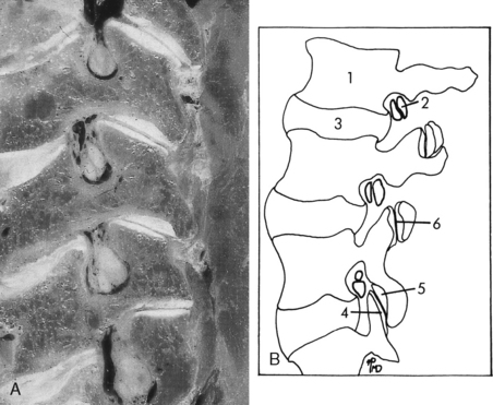
The spinal cord contains 8 cervical, 12 thoracic, 5 lumbar, 5 sacral, and 1 coccygeal pairs of spinal nerves. These nerves are rather easily identified on CT with intrathecal contrast or high-resolution MR. It is important to appreciate that C1, which is a sensory nerve, exits above the C1–C2 interspace so that the C2 nerve exits between C1 and C2, and so on. Thus, in the cervical spine the nerves running through the cervical neural foramina are the higher numbered cervical root (e.g., the C6 root goes through the C5–C6 foramen). At the cervicothoracic junction, the C8 nerve root exits between C7 and T1. Below this level it is the lower-numbered root going through the respective foramina. Thus, T1 exits between T1 and T2, and T12 exits between T12 and L1. In the lumbar spine the L1 root exits between L1 and L2 and so forth, so that the L5 root exits between L5 and S1. However, a funny thing happened on the way to creation. The bodies in the lumbar region became much longer. The nerve roots in this region leave the thecal sac right under the pedicle (Fig. 16-1), well above the interspace. Paracentral disk herniations in the lumbar region characteristically strike the root in the thecal sac that will exit below the interspace. This is because the disk space is inferior to the same numbered exiting root at that level. Thus, an L4–L5 disk herniation most often compresses the L5 root because the L4 root is already in the foramen. Far lateral herniated disks may compress the upper root; that is, an L4–L5 lateral or foraminal herniation can compress the L4 root. Larger disks can compress many roots in the thecal sac. Furthermore, disk fragments may migrate superiorly and compress the root exiting at the appropriate interspace, that is, an L4–L5 free fragment can compress the L4 root or a combination of both the L4 and L5 nerve roots.

Figure 16-1 Nerve roots in cervical neural foramina. A, Cervical roots. B, Lumbar roots (2) travel in the upper half of the foramen. 1, Vertebral body; 3, disk; 4, superior articular facet; 5, inferior articular facet; 6, facet joint.
(From Firooznia H, Golimbu C, Rafii M, et al: MR and CT of the musculoskeletal system, St Louis, Mosby-Year Book, 1992.)
An anatomic variation is the conjoined nerve root, which occurs in less than 5% of patients, with L5–S1 being the most common disk space at which this occurs. This normal variation consists usually of two nerve roots traveling in the same dural pouch and exiting through the same or through different foramina. The problem is really the radiologist’s. She or he should not mistake the conjoined root on myelography for an epidural defect with obliteration of the thecal sac below the conjoined root. The most significant mistake occurs on CT of the lumbar region without intrathecal contrast. Here conjoined roots can appear as disk herniations. The key is that the density of the conjoined root/cerebrospinal fluid (CSF) complex is similar to the thecal sac and not that of disk without intrathecal contrast. Furthermore, conjoined roots have a characteristic position as opposed to a disk herniation. Conjoined roots have been reported occasionally to enlarge the neural foramen. Today with MR, this normal variant is not usually a diagnostic problem.
In the cervical region, the disks generally compress the roots at the foramen at the same level. Thus, a C5–C6 disk compresses the C6 root. In the cervical region, the roots are in the lower portion of the foramen, whereas in the lumbar region they are in the upper aspect of the neural foramen. In the thoracic region, disk herniations may cause myelopathic changes; however, they can also produce thoracic radiculopathy. Lesions at the given thoracic spine body level might also produce sensory symptoms one to two segments below the compression. This is because the cord ends at approximately T12–L2 so that cord lesions result in neurologic deficits that are localized below their vertebral body anatomic location.
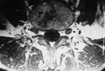
Each spinal nerve is divided into a dorsal or sensory root and a ventral or motor root. The dorsal root ganglion is a distal dilatation of the dorsal root just proximal to its joining with the ventral root to form the spinal nerve (Fig. 16-2).
Vertebrae
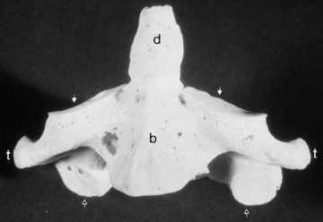
The generic vertebra is composed of the cylindrical vertebral body, which contains cancellous bone with marrow and fat, covered by a thin layer of compact cortical bone, and the vertebral arch or posterior elements, which include the pedicles, laminae, superior and inferior facets, transverse processes, and spinous process (Fig. 16-3). The vertebral configuration is modified in the different regions of the spine. The cervical vertebrae have their neural foramina between the transverse processes. The superior and inferior articular facets in the cervical region form the articular pillar (Fig. 16-4). The lower five cervical vertebrae have five joints connecting them. They are the intervertebral disk, two facet (zygapophyseal) joints, and two uncovertebral joints. The uncovertebral joints (neurocentral joints, joints of Luschka) originate from the lateral posterior portion of the vertebral body, articulate with the contiguous vertebral body, and insinuate themselves between the disk and the nerve root canal. The vertebral artery branches from the subclavian artery (V1 portion), enters the foramen transversarium at approximately C6, and travels superiorly (V2 portion) before exiting at C1–C2 (V3 portion) and then enters the cranial compartment (V4 portion).

Figure 16-3 Vertebral anatomy. This computed tomography scan of a lumbar vertebra serves as a model for a generalized vertebra. Pedicle (p), lamina (l), transverse process (t), basivertebral venous plexus (arrows), and spinous process (s) are labeled.
The first cervical vertebra (atlas) has no body but rather just an anterior arch connected to two lateral masses and a posterior arch (Fig. 16-5). On the upper surface of the posterior arch is a groove over which the vertebral artery courses after it leaves the foramen transversarium of C1. The vertebral arteries pass through the posterior atlanto-occipital membrane and course anterosuperiorly upward through the foramen magnum. As it pierces the dura the vertebral artery may be slightly narrowed, and this caliber change can serve as a marker for the beginning of the intradural V4 segment of the vertebral artery. The first spinal nerve exits here as well.

Figure 16-5 Axial view of atlas. The following structures are identified: anterior tubercle (a), posterior tubercle (p), foramen transversarium (+), transverse process (t), anterior arch (−), posterior arch (∼︀), sulcus for vertebral arteries (arrows). There are also holes in the lateral mass (+) for the vertebral arteries.
The second cervical vertebra, the axis, is unique, with a superior extension from its body termed the dens (odontoid process) (Fig. 16-6). The dens represents the lost vertebral body of the atlas. The articulation between the atlas and axis is composed of multiple synovial joints—one medial between the dens and the anterior arch, one on each side between the inferior articular facet of the lateral mass of the atlas and the superior facet of the axis, and multiple ones between the dens and the atlantoaxial ligaments (transverse, cruciate, and alar). Rheumatoid arthritis has a propensity for the atlantoaxial joint with pannus formation, leading to bone erosions and subluxations.

Figure 16-6 Anterior view of axis demonstrates dens (d), body (b), superior articular facets (arrows), inferior articular facets (open arrows), and transverse processes (t).
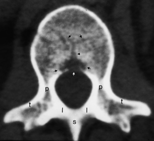
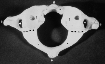
The thoracic vertebrae have an articulation on the transverse process for the rib and no foramen transversarium, whereas the lumbar vertebrae have neither a foramen transversarium nor a specific facet for the rib articulation. The lumbar vertebral articulations are composed of the lumbar disk and two facet joints posteriorly. The lateral recess of the lumbar spine is in the anterolateral portion of the spinal canal, with boundaries consisting of the posterior margin of the vertebral body and disk anteriorly, the medial margin of the pedicle laterally, and the superior articular facet, the medial insertion of the ligamentum flavum, the lamina, and the pars interarticularis posteriorly (Fig. 16-7).

Figure 16-7 Right posterior oblique film of Scottie dog. Right facet joint is seen (arrows). At the disk space below, components of the Scottie dog are identified: eye, right pedicle (+); neck, right pars interarticularis (p); ear, right superior articular facet (s); front leg, right inferior articular facet (i); body, lamina (b); nose, right transverse process (open arrow); tail, left superior articular facet (t); rear leg, left inferior articular facet (r). Ooops. Scottie had an accident … .
Intervertebral Disks
The diskovertebral complex is composed of three components: the cartilaginous endplate, annulus fibrosus, and nucleus pulposus. The endplate consists of a flat bony disk with an elevated rim (attached ring apophysis), which produces a central depression in the endplate occupied by hyaline cartilage.
The annulus fibrosus surrounds the nucleus pulposus (the remnant of the notochord). The nucleus is eccentrically located near the posterior surface of the disk. The lamellae of the annulus are fewer in number, thinner, and more closely packed posteriorly than anteriorly. This anatomic arrangement may account for the propensity for posterior disk herniation. The external fibers of the annulus are connected to the bone of the vertebral bodies by Sharpey’s fibers, which usually cannot be distinguished by imaging. Annular fibers also merge with both anterior and posterior longitudinal ligaments. Important ligaments of the vertebral column are (1) the anterior longitudinal ligament, running along the anterior aspect of the vertebral bodies; (2) the posterior longitudinal ligament, running along the posterior aspect of the vertebral bodies anterior to the thecal sac; (3) the ligamentum flavum, connecting the laminae and extending from the midline laterally to the facets; and (4) the interspinous ligament, joining the superior portion of the spinous process below to the inferior part of the spinous process above and meeting the ligamentum flavum in the midline (Fig. 16-8). There are also small ligaments in the neural foramen, which may play a role in foraminal stenosis.

Figure 16-8 A–C, Cryomicrotome anatomic sections of the lumbar spine in sagittal plane. Arrowheads, anterior longitudinal ligament; DRG, dorsal root ganglion; EF, epidural fat; EnR, exiting nerve root; IF, inferior facet; LF, ligamentum flavum; P, pedicle; PLL, posterior longitudinal ligament; small arrows, dura mater; SF, superior facet; SP, spinous process; TNR, traversing nerve root; VP, venous plexus.
Spinal Cord
The spinal cord extends from the medulla oblongata, at the level of the upper border of the atlas, to T12–L2, where it terminates in the conus medullaris. At the apex of the conus, continuous with the pia mater, is the filum terminale, which descends initially in the thecal sac and then becomes covered with adherent dura as it leaves the thecal sac to insert in the coccyx. The cauda equina emanates from the conus medullaris and contains the nerve roots of the lumbar and sacral nerves. The spinal cord has two enlargements in its course, one in the cervical region from approximately C4 to approximately T1 (cervical enlargement) and the other in the lower thoracic region from approximately T9 to T12 (lumbar enlargement). Do not mistake these normal expansions for a pathologic process. These enlargements correspond to the locations in the cord that supply the spinal nerves for the upper and lower extremities. There is also potentially a small dilation of the central canal of the cord in the conus region sometimes referred to as the terminal ventricle or fifth ventricle, which is seen in 2% to 3% of children under age 6 years.
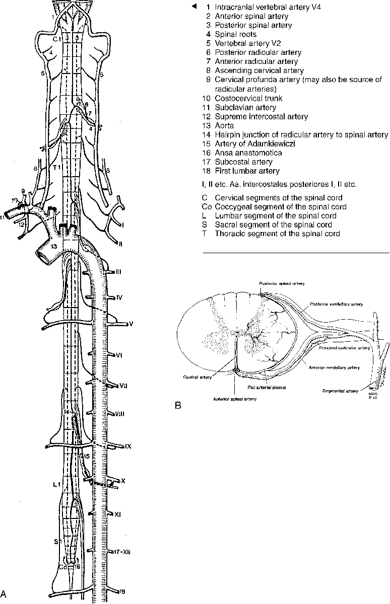
Blood Supply to the Spinal Cord
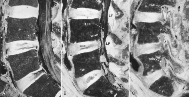
The blood supply to the spinal cord depends on the particular location (Fig. 16-9). In the cervical region the anterior spinal artery is formed by branches that originate from the vertebral arteries just before joining the basilar artery. The anterior spinal artery supplies the anterior two thirds of the spinal cord. In addition, paired posterior spinal arteries originate from the vertebral arteries and supply the dorsal portion of the cord (one sixth each). These two arterial systems do not usually have significant anastomoses between them. The anterior spinal artery supplies the anterior column of the central gray matter, the corticospinal, spinothalamic, and other tracts. The paired posterior spinal arteries supply the posterior columns and the posterior horn of the central gray matter. The anterior spinal artery is in the midline, whereas the posterior spinal arteries lie off the midline (see Fig. 16-9B). The anterior and posterior spinal arteries rarely originate at the same level. The caliber of the anterior spinal artery at a particular spinal level is proportional to the metabolic demands of the spinal gray matter.


Figure 16-9 Arterial anatomy of the spine. A, Schematic representation. B, Arterial blood supply at a single segment. Both the anterior and posterior are illustrated. This is not the typical arrangement. It is unusual for both anterior and posterior medullary arteries to enter at the same segment in any region of the cord. C, Spinal arteriogram. Injection into an intercostal artery (arrow is on catheter tip) reveals filling of artery of Adamkiewicz with its characteristic hairpin turn (curved arrow). Anterior spinal artery is filling (open arrows).
(A, From Nieuwenhuys R, Voogd J, van Huijen C: The human central nervous system: a synopsis and atlas, rev ed 3, Berlin, Springer-Verlag, 1988. B, From Krauss WE: Vascular anatomy of the spinal cord, Neurosurg Clin North Am 10:10, 1999.)
At the C3–C4, C5–C6, and C7–T1 levels, radicular feeders from the vertebral, ascending cervical (anterior to the transverse process), and deep cervical (posterior to the transverse process) arteries anastomose with the spinal arteries. The radicular feeders enter the thecal sac through the intervertebral foramina and divide into the anterior and posterior branches coursing with the nerve roots. Because they follow the nerve root, the spinal arteries have a sharper angle in the lumbar region than in the cervical region. However, not all spinal nerves have radicular arteries. The cervical and upper two thoracic levels comprise one vascular territory. The midthoracic region (T3–T7) is supplied by intercostal branches from the aorta/bronchial arteries, branches of the supreme intercostal arteries from the subclavian arteries, and lumbar arteries. This region may have a tenuous blood supply. The lower thoracolumbar region to the filum terminale is supplied by the artery of Adamkiewicz. It is commonly located on the left side between T9 and L2 (85% of the time) or between T5 and T8 (15% of the time). It enters the spinal canal with the nerve roots and makes a characteristic hairpin loop, giving off a small superior branch of the anterior spinal artery from the apex of the turn and a large descending branch, which supplies the anterior spinal cord and anastomoses with the posterior spinal arteries in the region of the conus medullaris.
Uncommonly, an artery named the artery of Lazorthes arises from the common or internal iliac arteries and accompanies one of the sacral roots of the cauda equina to supply the conus medullaris. The venous blood supply is comparable to the arterial blood supply with a variable amount of anterior and posterior spinal veins running with the spinal arteries.
RADIOLOGIC WORKUP
Myelography (see Chapter 1)
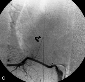
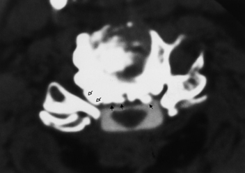
“What presently is the role for myelography?” Although not performed as often as it once was, myelography, almost always combined with CT (myelo-CT), is still a sensitive and useful technique for disk herniation and, more importantly, osteophytic impingement on cervical roots. Myelo-CT is excellent in patients with cervical radiculopathy for visualizing small spurs compressing nerve roots or in cases of cord compression (Fig. 16-10). Other roles include detecting root avulsions, CSF leaks, subarachnoid spread of tumor, small tumor implants on nerve roots, and arachnoiditis. The advantage of myelo-CT is the exquisite bone detail superimposed on the subarachnoid contrast. In the opinion of the authors, myelo-CT is more precise than MR at evaluating the effect of cervical spine uncovertebral joint disease on nerve roots. However, if you are the patient, do you want a spinal tap, with the high likelihood of a spinal headache and the possibility, although remote, of infection or other complications? Some patients report that the postmyelogram headache is worse than the backache before or after surgery. That is an advantage of MR, not to mention it is the method of choice for visualizing the spinal cord and soft tissues.

Figure 16-10 Osteophytic spur. Computed tomography myelography (myelo-CT) faithfully demonstrates osteophytic spurs both centrally (closed arrows) and laterally (open arrows). Note that the patient already had a laminectomy. Myelo-CT is a reliable method for detecting osteophytic impingement.
Patients in whom MR is contraindicated, such as persons with metallic implants or cardiac pacemakers, or those who cannot tolerate MR, can be easily examined by myelo-CT for nonintramedullary pathology. Metallic hardware for spine stabilization, such as pedicle screws and anterior metallic plates, degrades MR to a variable extent, worse at higher field strength (Fig. 16-11). Other potential uses are in cases where ambiguity in the diagnosis exists, such as for demonstrating on avulsed nerve roots or for distinguishing osteophytes from dessicated disks. MR is excellent at depicting compression of the cord and, although it cannot detect a functional spinal cord block with respect to intrathecal contrast, there is no potential for patients with a block deteriorating after spinal tap for myelography.

Figure 16-11 Magnetic resonance (MR) scan of pedicle screws. A, How can the MR show the pedicle screws so well? You thought we said that they obscure anatomy on MR images. The high signal on T2WI likely represents the screw tracks (arrowheads) from screws that have been removed. B, Axial postcontrast T1WI shows the correct anatomic placement of the screws in the pedicles but not extending beyond the vertebral body anterior margin.
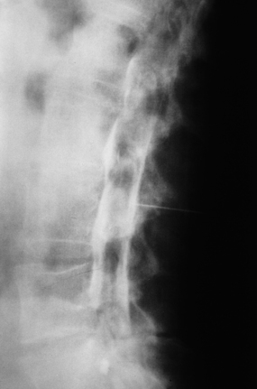
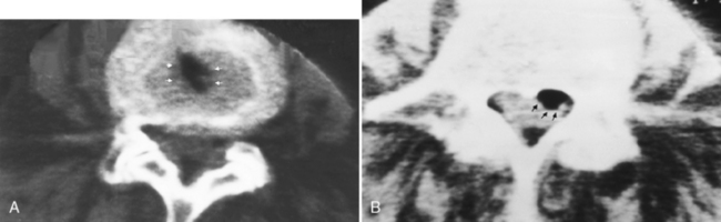
When you perform a myelogram, be very careful that the contrast agent is instilled in the appropriate compartment. Subdural injections of contrast are not uncommon, and myelograms performed with contrast in the subdural compartment can be misleading (Fig. 16-12). As contrast is instilled into the lumbar region, it is critical to visualize the individual nerve roots of the cauda equina. If these are not demonstrated, you are probably dealing with either a subdural injection or severe arachnoiditis. Another clue to a subdural injection is in the lateral projection, where subdural contrast may collect in the posterior aspect of the thecal sac, as opposed to its normal ventral position, in a patient in the prone position. In the thoracic region, the cord and its surrounding space should be apparent. Failure to separate cord density from surrounding contrast material again suggests subdural injection. The subdural space in the spine is continuous withthat of the brain. On CT, you may see contrast along the clivus, because of subdural injections.

Figure 16-12 Subdural injection. A lateral myelographic film reveals filling of subdural space. Note that the nerve roots are not clearly seen. There is contrast anterior and posterior to the thecal sac in a characteristic pattern indicating a subdural injection.
Epidural space extravasations are less common. Irregular streaky collections of contrast can be observed laterally throughout the lumbar region in an extrathecal location, sometimes following nerve roots well beyond the vertebral column, and occasionally in the epidural venous plexus.
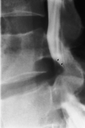
Disk herniation on myelography is diagnosed by displacement of the thecal sac or effacement of a root pouch (Fig. 16-13). It is important to evaluate the myelogram in the anteroposterior (AP), oblique, and lateral planes. A double density can be seen on the lateral radiograph in the paramedian herniated disk. The thecal sac at L5–S1 is convex at its lateral margin as it tapers to the sacrum. Concavity in this region should suggest disk herniation even if the roots do not appear to be effaced. You should appreciate that myelography without CT can be normal in cases of far lateral/foraminal disks and may be insensitive at the L5–S1 level when the cul-de-sac ends at or above this interspace.

Figure 16-13 Lateral myelogram of a large herniated disk. Thecal sac and nerve roots are abruptly cut off (arrows) by this large herniated disk.
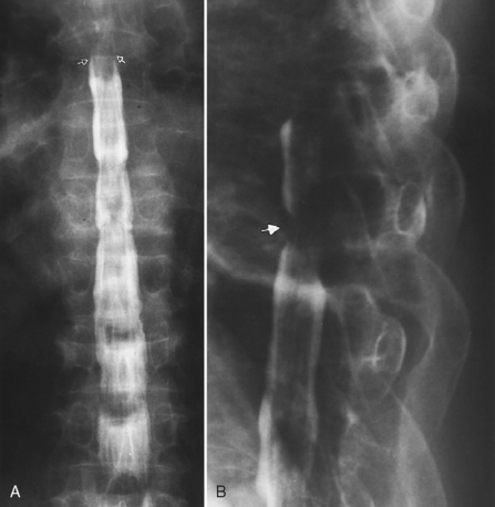
On AP myelographic films with an extradural lesion in the cervicothoracic zone, the spinal cord may appear to be enlarged (Fig. 16-14). It is most important to view lesions involving the cord in two planes! Many mistakes have been made by just gunning from the hip off the AP film. This is much less of a problem presently because myelography is usually performed in combination with CT.

Figure 16-14 Spinal block producing the appearance of an intramedullary process on anteroposterior (AP) myelogram. A, AP myelographic projection reveals a high-grade block to the flow of contrast in the thoracic region (arrows). The cord appears expanded with narrowing of the lateral contrast margins simulating an intramedullary process. B, Lateral projection demonstrates that this is an extradural tumor mass (arrow) compressing the cord.
Computed Tomography
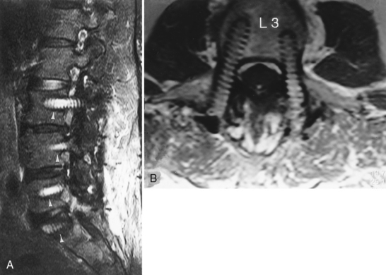
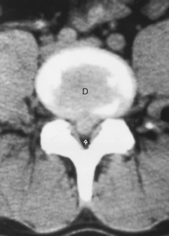
Just a short word concerning CT: Myelo-CT unambiguously reveals extradural bony lesions compressing the subarachnoid space, roots, and spinal cord. CT without intrathecal contrast is adequate for the lumbar region, where natural contrast exists between epidural fat, disk, and bone (Fig. 16-15). However, there is usually little contrast between the spinal cord and the subarachnoid space in the cervical and thoracic regions, so that intradural processes are suboptimally imaged without intrathecal contrast.

Figure 16-15 Herniated disk on unenhanced computed tomography scan. Huge central herniated disk is squashing the thecal sac (open white arrow). Herniated disk and the parent disk (D) have the same density.
The postmyelogram lumbar CT is best performed, if tolerated, with the patient in the prone position. This enables the contrast to pool in the anterior thecal sac and along the root pouches, making it most sensitive to root effacement by disk or bone. However, the supine position is more easily tolerated and in most cases is acceptable, especially after the patient has turned on the table to mix CSF and iodinated contrast. Multiplanar reconstructions of thin-section source data are critical. Imaging is ideally performed with bone and soft-tissue windows to optimize evaluation of disk and bone.
Diskography
The use of diskography is a most controversial topic. The procedure calls for injection of contrast material within the nucleus pulposus itself. After injection, plain radiographs are made and additional CT images can be obtained. There are several observations to be made that include whether the contrast is confined by the annulus, streaks into the annulus, or leaks into the epidural space. Here you may be able to diagnose an unsuspected annular fissure. Equally important is the reproduction of patient symptoms from the injection of contrast material. Thus, the injector must have enough experience to perform the technique in a reproducible manner, and hopefully the injectee will have a reproducible response. Most physicians performing these procedures do not identify to the patient the level at which they are injecting or even when they are injecting so as to determine if there is a diskogenic source to the pain and at what level. Do these procedures add anything? For one thing, they are useful in cases of a disconnect between considerable pain and no definitive imaging findings. Potentially, you can find the level that is producing the symptoms. A second possible useful application is in cases with multiple disk herniations and no definitive notion of which level is the symptomatic culprit.
Low Tech: Plain Spine Films
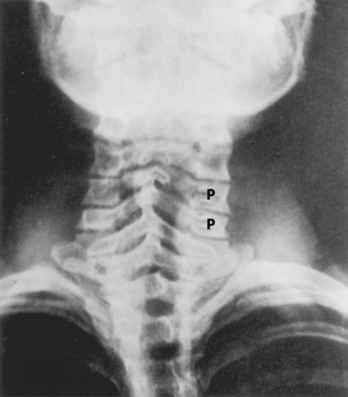
Plain spine films are still performed and are useful, particularly when looking for small fractures in cases of trauma and to check alignment of the vertebral bodies, the position of bone grafts, pedicle screws, cages, plates, and abnormal motion of vertebrae during flexion and extension. Every view contains potential aids in demonstrating disease, but we will briefly focus on a few specific regions and important information to be gained. In the AP and oblique views of the cervical spine, the uncovertebral and facet joints and their relationship to the neural foramina are best demonstrated (Fig. 16-16). There is reasonably good correlation between uncovertebral spurs and myelographic impingement associated with radiculopathy. Alignment of the spinous processes should be assessed for rotational injury to the spine. Subluxations caused by trauma can be detected by noting differences in distance between the spinous process tips of C5–C6 and C6–C7 and are important because the lateral radiograph may not visualize C6–C7. Unilateral facet dislocations produce rotation of the spinous processes in the transverse plane.

Figure 16-16 Anteroposterior view of cervical spine. Lateral masses of C1 (m), dens (d), body of C2 (b), bifid spinous process (s) of C4, uncovertebral joint (arrows), and a neural foramen (arrowhead) are identified.
The lateral cervical spine radiograph provides an excellent view of the odontoid process and the anterior arch of C1. The distance between the anterior aspect of the odontoid and the posterior surface of the anterior arch of C1 should not be greater than 3 mm in an adult or 5 mm in a child. Alignment of the spine and the disk spaces is easily evaluated with the lateral view. The minimal sagittal diameter of the cervical spinal canal between C3 and T1 is 13 mm corrected for magnification. Pay attention to the distance between the back of the articular facets and the spinolaminar line on a nonrotated cervical spine lateral view. If there is little or no distance between the posterior margins of the spinal facets of the cervical vertebra and the spinolaminar line, think spinal stenosis! With the lateral view, you receive at no extra charge the prevertebral soft tissues and the sella turcica. Occasionally, you will note unexpected findings, including an enlarged sella or prevertebral mass. A “swimmer’s” view is used to study C7–T1 if it cannot be visualized on the lateral view, and consists of a lateral view with the tube-side arm depressed and the film-side arm elevated. Ossification of the posterior longitudinal ligament (OPLL) and diffuse idiopathic skeletal hyperostosis (DISH) are identified on the lateral radiograph.
Thoracic AP films visualize the pedicles and vertebral bodies. Carefully, determine whether there is pedicle erosion, a sign of metastatic disease, or whether the interpediculate distance is abnormal. This indicates an intraspinal lesion or a possible congenital spinal problem. The lateral thoracic radiograph provides information on thoracic alignment (scoliosis), abnormal calcifications in a disk or in a meningioma, and the state of the vertebral body and its associated disk spaces.
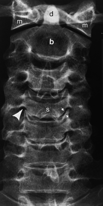
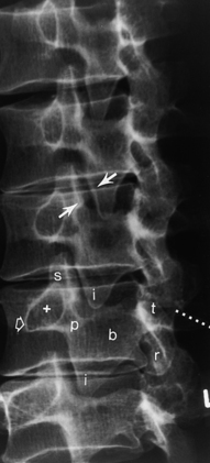
Information obtained from the lumbar spine AP and lateral films is similar to that of the thoracic spine; however, the oblique radiographs produce the well-known “Scottie dog,” which provides an excellent view of the pars interarticularis. In the right posterior oblique view the right superior articular facet is the dog’s ear, the right pedicle is the eye, the right transverse process is the nose, the right inferior articular facet is the front leg, the right lamina is the body, the left superior articular facet is the tail, and the left inferior articular facet is the hind leg (see Fig. 16-7). Fractures of the “neck” of the dog indicate spondylolysis (Fig. 16-17; see Fig. 16-7). Spondylolysis is associated with spondylolisthesis (anterior slippage of a vertebral body), both of which are readily detectable on plain films and are discussed later in this chapter.

Figure 16-17 Spondylolysis and spondylolisthesis. A, Sagittal T1-weighted image (T1WI) beautifully illustrates spondylolisthesis of L5 on S1. Note the elongation of the pedicle (arrow) and the pars interarticularis defect (open arrow). The disk (asterisk) is compressing the nerve root in the compromised neural foramen (arrowhead). Normally the foramen has a keyhole appearance on the sagittal image, with an abundance of fat, whereas in spondylolisthesis the orientation of the neural foramen goes from vertical to horizontal and little foraminal fat can be seen. B, Sagittal T1WI shows grade 3 spondylolisthesis with endplate degenerative changes at L5–S1. C, The effect on the thecal sac is better illustrated on the sagittal T2WI. D, In another patient, a pars defect is well depicted on the axial computed tomography scan on the right side as well as a healed sclerotic old pars defect on the left side. The horizontal orientation of the right defect indicates that this is unlikely to be a facet joint.
NORMAL MAGNETIC RESONANCE APPEARANCE OF THE SPINE
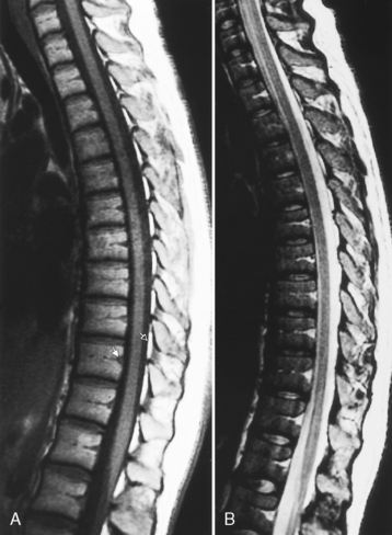
The beauty of MR is its ability to provide multiplanar images of both the bone and soft tissues of the spine. In the adult, the normal vertebral marrow generally has intermediate to high signal intensity on T1-weighted imaging (T1WI) and low signal intensity on conventional T2-weighted imaging (T2WI) with bone marrow hypointense to the disk and CSF hyperintense (Fig. 16-18). This appearance is variable, depending on the exact pulse sequence and the age of the patient. On T2WI fast spin-echo images, the normal vertebral marrow is high intensity, making lesion detection in the vertebral body more challenging. Fat saturation or short tau inversion recovery (STIR) sequences are important when vertebral body lesions are suspected and fast spin-echo techniques are being employed. However, the saturation may not be uniform, particularly when large fields of view are employed.

Figure 16-18 Normal spine magnetic resonance scan. A, T1-weighted image (T1WI) shows the vertebral bodies to be of higher intensity than the disks. Cerebrospinal fluid (CSF) is low intensity. The spinal cord is higher in intensity than the CSF. The basivertebral plexus (closed arrow) and the epidural fat (open arrow) are identified. B, Conventional T2WI reveals the vertebral bodies to be lower in intensity compared with the disks. The CSF is high intensity and the spinal cord is low intensity. The basivertebral plexus is high intensity.
In children, the marrow is lower in intensity than in adults because of the low fat content of hematopoietic marrow. In young adults, a small region of high intensity on T1WI is observed at the entry of the basivertebral veins. With aging, the hematopoietic (red) marrow is gradually converted to fatty (yellow) marrow. In older patients, this process can result in focal regions of high intensity on T1WI (focal fatty replacement) with a heterogeneous appearance. In children, the normal marrow may enhance; however, in adults normal marrow does not enhance significantly. In patients with anemia, fatty marrow is replaced by hematopoietic marrow with decreased and heterogeneous signal intensity on T1WI.
The epidural plexus of veins has a variable appearance on MR, depending on the particular pulse sequence used. The plexus enhances. Occasionally, this plexus may be prominent and masquerade as a disk. In this situation enhancement is useful. A prominent venous plexus may also be visualized above or below a herniated disk or in spinal stenosis.
DEGENERATIVE DISEASES
Unlike great wines, the spinal column does not improve with age—it degenerates. It is important to separate the process of disk degeneration from disk herniation. The pathophysiology of the degenerative process consists of loss of water in the nucleus pulposus and decreased tissue resiliency (intervertebral chondrosis) with decrease in the height and signal intensity of the disk. Early MR abnormalities representing disk degeneration include infolding of the anterior annulus and a hypointense central dot within the disk on T2WI. Disk degeneration is noticeable by age 20 years.
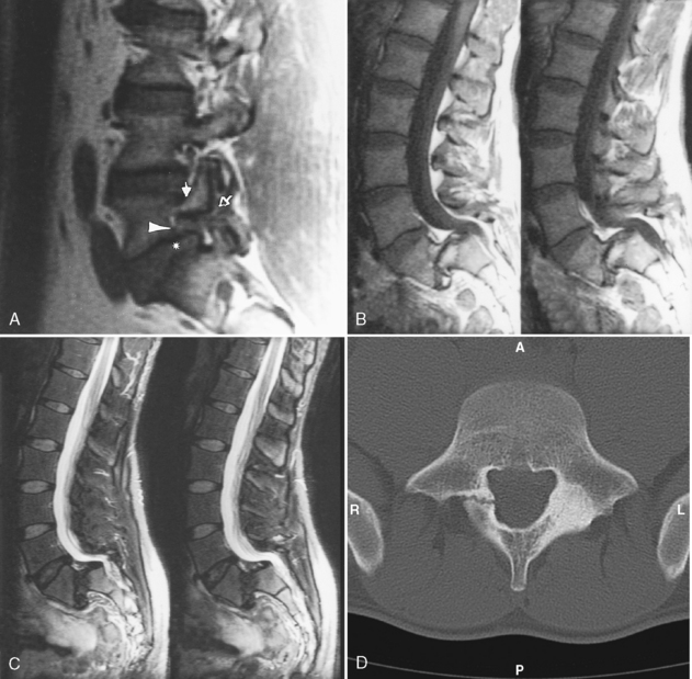
Initially, the nucleus pulposus is soft and gelatinous; however, with aging it is replaced by fibrocartilage, and the distinction between nucleus and annulus fibrosus becomes less well defined. The cartilaginous endplate becomes fissured and more hyalinized. The annulus, which is initially attached to the anterior and posterior longitudinal ligaments, loses its lamellar configuration and develops fissures. The cracks have negative pressure so that gas, primarily nitrogen, comes out of solution and deposits in the intervertebral disk, close to the subchondral bone plate or in other locations. This is termed the vacuum (cleft) phenomenon (Fig. 16-19). These degenerative changes permit disk material to bulge and subsequently to herniate. Remember that disk herniation may also occur in the absence of significant disk degeneration.

Figure 16-19 Vacuum phenomenon. A, Very low-density gas (arrows) can be seen within the disk. B, In this case the gas (arrows) is the only evidence of the herniation, which is displacing the thecal sac to the right.
Disk calcification commonly occurs in the elderly and is part of the normal aging process. It is also associated with other conditions (Box 16-1). Increased intensity of the disk on T1WI can be seen uncommonly with mild calcification associated with degeneration. As calcification increases, the intensity on T1WI decreases.

Full access? Get Clinical Tree

