Chapter 2 Electrophysical and thermal principles
INTRODUCTION
Electrophysical agents are used by physiotherapists to treat a wide variety of conditions. These agents include both electromagnetic and sound waves, in addition to muscle- and nerve-stimulating currents. In part, these techniques are used to induce tissue heating. This chapter contains, in simple terms, an introduction to the effects of heat on tissue and the basic physics necessary for the understanding of the remainder of the book. The electrical properties of cells and the implications for electrotherapy are described in Chapter 3.
It became the accepted view that heat can be regarded as a form of energy which is interchangeable with other forms such as electrical or mechanical energy. The theory supposed that, when a body is heated, the rise in temperature is due to the increased energy of motion of molecules in that body. The theory went further and explained the transmission of radiant energy from one body to another, as from the sun to an individual on earth. Evidence was found in favour of the supposition that light is an electromagnetic wave, and exactly the same evidence was adduced with regard to radiant energy. Apart from the fact that radiant heat waves (e.g. infrared radiations) have a longer wavelength than light waves, their physical characteristics are the same. It was therefore suggested that molecules of a hot body are in a state of rapid vibration, or are the centre of rapid periodic disturbances, producing electromagnetic waves, and that these waves travel between the hot body and the receiving body, causing a similar motion in the molecules. The sensation of heat may thus be excited in an organism by waves of radiant heat energy which emanate from a hot object, just as the sense of sight is excited by waves of light which arise from a luminous object.
WAVE MOTION
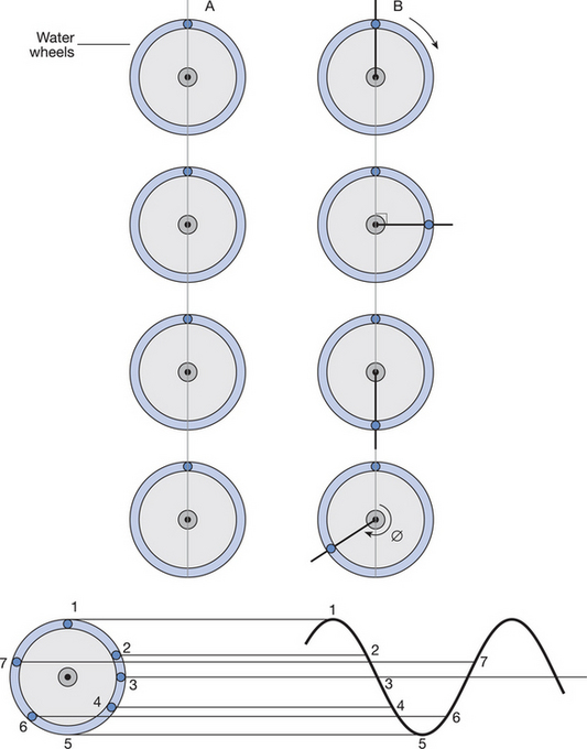
An easy way to demonstrate wave motion is to use a Slinky spring toy. Two types of wave exist: transverse waves, which can be mimicked by raising and lowering one end of the spring rapidly, as shown in Figure 2.1, and longitudinal waves, which can be demonstrated by extending the spring along its length and then letting it go (Fig. 2.2). Water waves, the motion of a violin string and electromagnetic waves – as used in short-wave diathermy, infrared and interferential current therapy – are examples of transverse waves. Sound, as used in ultrasound therapy, propagates mainly as longitudinal waves.
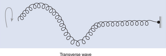
Figure 2.1 If a spring that is attached at one end is flicked up and down, a transverse wave is produced.
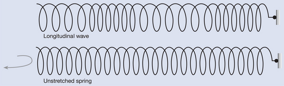
Figure 2.2 Extending a spring along its length and letting it go again produces a longitudinal wave.
It is much more difficult to picture a longitudinal wave than a transverse wave. If the spring with the wave travelling down it (Fig. 2.2) is compared with an unstretched spring, some regions can be seen where the coils are closer together, and other regions where the coils are further apart. The part of the spring where the coils are closely spaced is called a region of compression, and the region where they are separated more widely, is the rarefaction region.


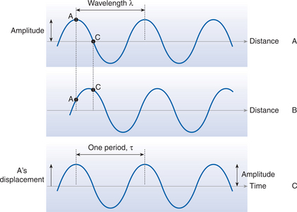
The distance between two adjacent wave crests is the wavelength (λ).
Figure 2.3A and B show a wave frozen at two moments, a short time apart. It can be seen that the different points on the wave have changed position relative to the central line but have not moved in space. In fact, if you tracked the motion of point A over several periods, the movement up and down would look like the picture shown in Figure 2.3C. The speed at which the wave crests move is known as the wave speed. As the wave moves a wavelength (λ) in one cycle, and as one cycle takes a time equal to the period t, then the wave speed (c) is given by the equation:

It is known that 1/t is the same as the frequency f, and so:

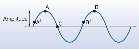
In Figure 2.4, points A and B on the wave (or, equally, A1 and B1) are moving in the same way and will reach the crest (or trough) together. These points are said to be in phase with each other. The movement from A to B (or A1 to B1) represents one cycle of the wave motion. A and C, however, are not in phase: C is a quarter of a cycle ahead of A and they are said to have a phase difference (ϕ) of a quarter cycle. Phase is usually expressed as an angle, where a complete cycle is 2π radians (or 360°). A quarter cycle therefore represents a phase difference of π/2 radians (90°). This is illustrated in Figure 2.5.
REFLECTION AND REFRACTION OF WAVES
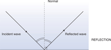
When waves travelling through a medium arrive at the surface between two media, some of the energy is reflected back into the first medium and some is transmitted through into the second medium. The proportion of the total energy that is reflected is determined by the properties of the two media involved. Figure 2.6 shows what happens when waves are reflected by a flat (plane) surface. An imaginary line that is perpendicular to the surface is called the normal. The law of reflection states that the angle between the incident (incoming) wave and the normal is always equal to the angle between the reflected wave and the normal. If the incident wave is at normal incidence (perpendicular to the surface), the wave is reflected back along its path.
The waves that are transmitted into the second medium may also undergo refraction. This is the bending of light towards the normal when it travels from one medium into one in which the wave speed is lower, or away from the normal when the wave speed in the second medium is higher (Fig. 2.7). For example, light bends towards the normal as it enters water from air since it travels more slowly in water than in air, and so a swimming pool may appear shallower than it really is.
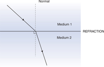
Figure 2.7 When a beam passes from one medium to another it can be refracted (i.e. it changes its direction).
As has been discussed earlier, waves carry energy. There are conditions, however, in which the transport of energy can be stopped, and the energy can be localised. This happens in a standing (stationary) wave. A standing wave is produced when an incident wave meets a returning reflected wave with the same amplitude. When the two waves meet, the total amplitude is the sum of the two individual amplitudes. Thus, as can be seen in Figure 2.8A, if the trough of one wave coincides with the crest of the other, the two waves cancel each other out. If, however, the crest of one meets the crest of the other, the wave motion is reinforced (Fig. 2.8B) and the total amplitude doubles. In the reinforced standing wave there are points that always have zero amplitude; these are called nodes. Similarly, there are points that always have the greatest amplitude, and these are called antinodes. Nodes and antinodes are shown in Figure 2.8B. The distance between adjacent nodes, or adjacent antinodes, is one-half of the wavelength (λ/2).

ELECTRICITY AND MAGNETISM
ELECTRICITY
Matter is made up of atoms, an atom being the smallest particle of an element that can be identified as being from that element. The atom consists of a positively charged central nucleus (made up of positively charged protons and uncharged neutrons), with negatively charged particles (electrons) orbiting around it, resembling a miniature solar system. An atom contains as many protons as there are electrons, and so has no net charge. If this balance is destroyed, the atom has a non-zero net charge and is called an ion. If an electron is removed from the atom it becomes a positive ion, and if an electron is added the atom becomes a negative ion.
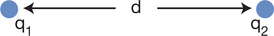
The force between two particles of charge q1 and q2 is proportional to the product of q1 and q2 (q1 × q2), and inversely proportional to the distance between them (d) squared (Fig. 2.9). Thus, the force is proportional to q1q2/d2. The constant of proportionality (i.e. the invariant number) necessary to allow one to calculate the force between two charges is 1/4πɛ, where ɛ is the permittivity of the medium containing the two charges:


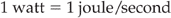
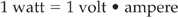
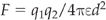
Electric fields
An electric field exists around any charged particle. If a smaller charge that is free to move is placed in the field, the paths it will move along are called lines of force (or field lines). Examples of fields and their patterns are shown in Figure 2.10.
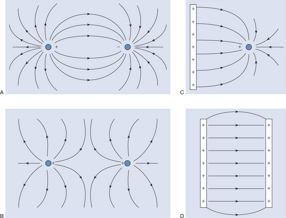
If E is the same throughout a field, it is said to be uniform. In this case, the field lines are parallel to each other as shown in Figure 2.10D. If a charged particle is moved in this field, work is done on it, unless it moves perpendicular to the field lines. This is somewhat analogous to moving a ball around on Earth. If the ball is always kept at the same height, and moved horizontally, its potential energy remains constant. If the ball is raised or lowered, its potential energy is changed. The ball has no potential energy when it lies on the ground. In a non-uniform field where the lines are not parallel, moving a charged particle always results in a change of potential energy. The electric potential, V, is defined as the potential energy per unit charge of a positively charged particle placed at that point. Electric potential is measured in units of volts. As the position at which the electric potential energy is zero is taken as infinity, another way of thinking of the electrical potential at a point is as the work done in moving the charge to that point from infinity. In practice it is easier to compare the electrical potential at two points in the field than to consider infinity. The difference in the work required to move a charge from infinity to a point, A, and that required to move it to another point, B, is called the potential difference (p.d.) between the two points; this is also measured in volts. The p.d. is best thought of as a kind of pressure difference. Between the two points there will be a gradient in potential (just as there is a pressure gradient between the top and bottom of a waterfall). This gradient is described in units of volts/metre. In a uniform field between parallel plates with potential difference V, and separation d, the potential gradient is given by V/d. If a particle of charge q is moved from one plate to another, the work done is qV. Work is force × distance, and so the force, F, is given by:

As the electric field strength, E, is given by:

Electric current
An electric current is the flow of electric charge (usually electrons). In some materials (e.g. metals) where the atoms are bound into a lattice structure, the charge is carried by electrons. In materials in which the atoms are free to move, the charge is carried by ions. A liquid in which the ions are the charge carriers is called an electrolyte. An insulator is a material that has no free charge carriers, and so is unable to carry an electric current. Current is measured using an ammeter, and the unit in which it is given is the ampere. An ampere represents 1 coulomb of charge flowing through a point in 1 second.
Resistance and Ohm’s law


From the definition given it is known that a coulomb/second is an ampere. So, therefore:

In other words, the electrical power developed in a circuit is given by:
where V is in volts, I is in amperes, and the power is in watts.


are equivalent equations, where W is in watts, V is in volts and R is in ohms.


Stay updated, free articles. Join our Telegram channel

Full access? Get Clinical Tree


