Fig. 9.1
The planar pantograph haptic system integrated with a mouse
The device is powered by two precious metal brushed 40 W DC-motors from Portescap (Model 25GT2R82-222E) through capstan cable transmissions which provide a 26:1 gearing ratio with minimum friction and excellent back drivability (back-drivable friction is below 0.2 N). Incremental encoders at the joints monitor the position changes of the device tip, while torque sensors measure the torque at each motor output shaft. The specifications of the device are shown in Table 9.1.
Table 9.1
Specifications of the planar haptic device
Property | Value |
|---|---|
Actuator | 40 W DC motors |
Position resolution | <0.05 mm |
Back-drivable friction | <0.2 N |
Peak force | 26 N |
Continues stall force | 3.9 N |
Workspace | 340 × 250 mm |
The haptic system end-tip has been interfaced with a mouse to form the assistive interface for the GUI based interactions. To monitor the exchange of forces between the assistive system and user’s hand a force sensor has been installed between the mouse and the haptic device. The cost of the prototype haptic device is 1300€ excluding the cost of the 6DOF F/T sensor (5,000€). This additional cost of the force torque sensor can be significantly reduced by replacing it with a two axis load cell with a cost of approximately 500€. Although a 2DOF load cell is sufficient the 6DOF sensor was used in this study as it was already available in our laboratory.
9.2.2 Device Kinematics
The kinematic configuration of the assistive haptic device is presented in Fig. 9.2. The position vector of the device tip with respect to the base frame O(x o , y o , z o ) is denoted by x t . We can obtain x t as a function of the active joint angles qi, i = 1, 2 and the upper link angle qu:
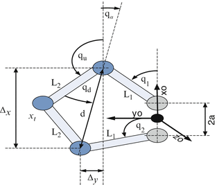
![$$ {\mathbf{x}}_{\mathbf{t}}=\left[\begin{array}{l}\hfill \mathrm{a}+{\mathrm{L}}_1 \cos \left({\mathrm{q}}_1\right)+{\mathrm{L}}_2 \cos \left({\mathrm{q}}_{\mathrm{u}}\right)\hfill \\{\mathrm{L}}_1 \sin \left({\mathrm{q}}_1\right)+{\mathrm{L}}_2 \sin \left({\mathrm{q}}_{\mathrm{u}}\right)\hfill \end{array}\right] $$](/wp-content/uploads/2016/11/A324794_1_En_9_Chapter_Equ1.gif)
where L1, L2 are the lengths of links and a is the location, along the X-axis, of the proximal joints of the inner links with respect to the base frame. The upper link angle qu can be determined using the geometry of the five bar mechanism qu = π − qd − qα.
Fig. 9.2
The kinematic geometry of the haptic device
(9.1)
The angle qd can be computed from the triangle formed by the outer links and the line joining the distal joints of the inner links  while angle qα is given by
  . L2, d and Δx, Δy represent the length of the distal link, the length of the line joining the distal joints of the inner links and the x, y distances between the distal joints of the inner links respectively. Substituting qu in (9.1) and directly differentiating the final expression of the forward kinematics yields the device Jacobian which relates the handle tip velocity to the two active joint velocities.

The dynamic behavior of the haptic device is finally described by:
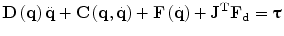
where the newly introduced notations describe: τ the generalized joint torque vector, D(q) the inertia matrix,  the coriolis/centripetal vector,
  the friction vector, F d is the force that the device generates at the end-tip and J T is the transpose Jacobian of the haptic device.
while angle qα is given by . L2, d and Δx, Δy represent the length of the distal link, the length of the line joining the distal joints of the inner links and the x, y distances between the distal joints of the inner links respectively. Substituting qu in (9.1) and directly differentiating the final expression of the forward kinematics yields the device Jacobian which relates the handle tip velocity to the two active joint velocities.(9.2)
(9.3)
the coriolis/centripetal vector, the friction vector, F d is the force that the device generates at the end-tip and J T is the transpose Jacobian of the haptic device.9.2.3 Assistive Control Scheme
The haptic device and its control scheme aims to aid a subject with motion coordination difficulties to interact with GUIs using a mouse by assisting the movements in the trajectory regions where motion is weak. We introduce the assistive control for the haptic device by initially considering the 1DOF linear mechanical system shown in Fig. 9.3.
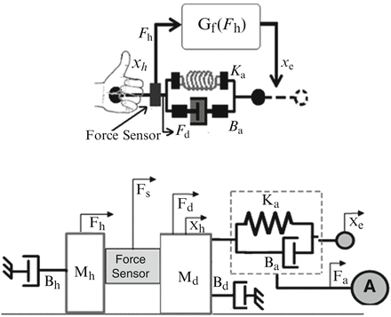
Fig. 9.3
User hand/device interaction diagram (top) and conceptual 1DOF linear model of the proposed assistive/suppression control law (bottom)
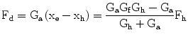
The extension of the concept to the full system will be discussed in the next section. In Fig. 9.3, mass Mh and damper Bh resemble the mass and damping properties of the human forearm and hand segments (mouse motions are primary generated by the movement of the elbow, wrist and finger joints). The user mass/damper block is fixed to the device end-tip through a force sensor which monitors the forces exchanged between the user and the haptic device. The device itself is represented by the mass/damper network denoted by Md and Bd. The spring/damper arrangement indicated by Ka, Ba is a virtual spring/damper group which is attached to the device tip at its one end point and represents the assistive control network. The remaining notations introduced in Fig. 9.3 are; Fh the force applied by the user, Fd the force provided by the device, Fs the force measured by the sensor, Fa the force generated by the actuator A, Xh the current device end-tip position and Xe the assistive network (Ka, Ba) grounding position which is dynamically updated according to the user effort and intended motion.
9.2.3.1 Assistive Controller Description
Let now assume that the subject’s hand is applying a force Fh through the mouse, while the haptic device is exerting a force Fd. The difference between these two forces is measured as the force sensor Fs = Fh − Fd. To provide the assistive functionality the amplitude and the direction of the assistive force needs to be determined. It is reasonable to use the direction of Fh to determine the direction of the user’s intended motion. The force applied by the user Fh can then be computed from the measured force Fs as follows:

(9.4)
To generate an assistive force in the user’s intended direction of movement, the assistive control network, represented by the spring/damper group (Ka, Ba) is used. One end of this virtual spring/damper system is rigidly linked to the device end-tip, while its second end is free to move; its position Xe is determined using the user’s effort and intended motion. In particular, the desired position Xe of the assistive network grounding end point is updated using the user force Fh. This can be written as:

where Gf represents the transfer function between the force exerted by the user and the grounding end point position. A possible transfer function Gf which can be used is the simple integrator  . The motivation behind the simple integrator is based on the idea that the accumulation of forces applied by the user can give a good indication/estimation of the user motion intention/direction and therefore it can be used to update Xe towards this direction. Other transfer function candidates include double integrators or other higher order controllers which could in addition permit shaping of the frequency response, e.g. preventing any tremor noise from entering the estimation of the intention of motion. As ataxia subjects do not suffer for this kind of tremor noise a simple integrator was experimentally proved (see section IV) to be adequate in this case.
(9.5)
. The motivation behind the simple integrator is based on the idea that the accumulation of forces applied by the user can give a good indication/estimation of the user motion intention/direction and therefore it can be used to update Xe towards this direction. Other transfer function candidates include double integrators or other higher order controllers which could in addition permit shaping of the frequency response, e.g. preventing any tremor noise from entering the estimation of the intention of motion. As ataxia subjects do not suffer for this kind of tremor noise a simple integrator was experimentally proved (see section IV) to be adequate in this case.The perturbation of the free end of assistive spring/damper network will trigger the generation of forces attracting the device end-tip towards the position Xe of the free end-point. In other words the device will generate a force Fd pulling towards Xe, which from the user’s point of view will be perceived as a force assisting his/her movement (the direction of the perturbation of Xe has been selected to coincide with the direction of the user’s applied force Fh). The pulling force is determined by the properties of the virtual assistive spring/damper (Ka, Ba) and is written as:
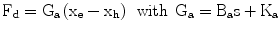
(9.6)
To exert the assistive force Fd at the device tip we select an actuator control signal as follows:
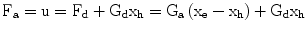
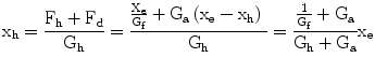
where the term Gdxh with Gd = Mds2 + Bds is added to compensate for the device dynamics. This pulling force Fd together with the force applied by the user Fh, drives the position of the pair (Haptic device + user’s hand) Xh towards Xe . It can be written:

where Gh = Mhs2 + Bhs resembles the mass and damping properties of the human hand/finger segments. By injecting Fh, Fd from (9.5) and (9.6) into (9.8) the position Xh can be obtained as a function of Xe.
Similarly by substituting Xh and Xe from (9.5) and (9.8) in (9.6) the assistive force Fd developed by the device can be derived as a function of the human applied force Fh.
Substituting Gh, Ga and Gf into (9.9) and (9.10) xh and Fd can be obtained as a function of the device, the human arm and the assistive network parameters.
(9.7)
(9.8)
(9.9)
(9.10)
9.2.3.2 Stability Analysis and Assistive Gain Selection
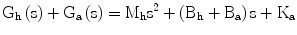
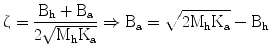
This characteristic equation is subject to change due to variations in Gh(s) . This is due to the variability in the mass and damping coefficients of the human arm Mh and Bh. If (Bh + Ba) > 0 and Ka > 0, then Gh(s) is Hurwitz. We may write:
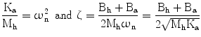
where ωn is the natural frequency for a stable, second-order, closed-loop system and ζ is the damping ratio. Through the control parameters of the assistive spring network (Ka, Ba), we have independent regulation of the natural frequency and damping ratio. We choose a desired  such that the system is underdamped. Therefore from (9.11) we can obtain:
The parameters of the assistive control law (Ka, Ba) are selected by considering the desired system bandwidth and damping ratio. Since the system and controller are used as a mouse based motion assistive device it is sensible to select the (Ka, Ba) gains such that the bandwidth of the system is greater than the maximum motion frequency during mouse based interaction movements (1–2 Hz). For this simulation study a bandwidth of ∼ 5 Hz (ωn = 30 rad/s) was considered for the 1DOF system presented in Fig. 9.3. The assistive network parameters were determined from (9.11) and (9.12) as Ka = 10 N/cm and Ba30 N s/cm. The mass and damping properties of the human hand/finger were set as Mh = 1 Kg, Bh = 0. The level of damping at the wrist and finger joints during voluntary movements is greatly affected by many factors the most important of which are; the mean level of muscle activation and the angular velocity of the joint [30]. Therefore, the value of the joint damping is a highly uncertain parameter with its maximum level being of an order greater than the minimum. Various studies [32–35] reports damping ratios for the forearm joints (elbow, wrist and finger joints) in the range of 0.1–1.0. By setting Bh = 0 the worst case condition in terms of system stability (hand/finger represented by a pure mass) is applied.
(9.11)
such that the system is underdamped. Therefore from (9.11) we can obtain:(9.12)
9.2.3.3 Assistive Controller Validation
To test the assistive control scheme, simulation studies were carried out on the 1DOF system shown in Fig. 9.3. The gain parameters used were those reported in the previous section. Here, a step like force input lasting for 0.2 s as shown in Fig. 9.4 (top graph) was used to trigger the 1DOF system.
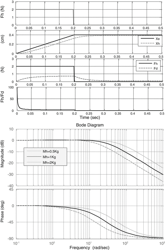
Fig. 9.4
The simulated responses of the 1DOF assistive control system
The top graph in Fig. 9.4 depicts the resultant perturbation of the grounded end of the assistive spring/damper group Xe and the dynamic behaviour of Xh towards Xe (dashed line). The displacement of Xe triggers the generation of force which pulls the device tip Xh towards the position Xe.
The attracting force Fd plotted against the force applied by the human Fh is shown in the following graph, Fig. 9.4. It increases with the application of the human force Fh to assist the motion and declines as soon as the human force is removed and the device position Xh reaches the target point Xe. The fourth graph in Fig. 9.4 presents the ratio  which can be seen as the reciprocal of the assistive ratio. A high value indicates the absence of assistive forces, while low values reveal their existence. It can be seen that the reciprocal of the assistive ratio is high during the application of the human force, but rapidly declines indicating the rise of the assistive force component.
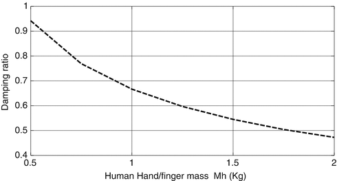
which can be seen as the reciprocal of the assistive ratio. A high value indicates the absence of assistive forces, while low values reveal their existence. It can be seen that the reciprocal of the assistive ratio is high during the application of the human force, but rapidly declines indicating the rise of the assistive force component.The Bode diagram in Fig. 9.4 presents the effect of the variation of the mass of the human hand/finger (0.5 Kg < Mh < 2 Kg) to the bandwidth of  dynamics demonstrating a bandwidth of ∼ 5 Hz (30 rad/s) for a nominal mass of Mh = 1Kg . In Fig. 9.5 the variation of the damping ratio of
  dynamics is presented as a function of the mass of the human hand/finger Mh. These simulation results demonstrate the potential of the proposed scheme as an assistive controller when triggered by the application of the human force.
dynamics demonstrating a bandwidth of ∼ 5 Hz (30 rad/s) for a nominal mass of Mh = 1Kg . In Fig. 9.5 the variation of the damping ratio of dynamics is presented as a function of the mass of the human hand/finger Mh. These simulation results demonstrate the potential of the proposed scheme as an assistive controller when triggered by the application of the human force.Fig. 9.5
 Effective Neural Representations for Brain-Mediated Human-Robot Interactions
 Considering Limb Impedance in the Design and Control of Prosthetic Devices
 Robotic Systems for Gait Rehabilitation
 State of the Art and Perspectives of Ultrasound Imaging as a Human-Machine Interface
 A Human Augmentation Approach to Gait Restoration
 Enhancing Recovery of Sensorimotor Functions: The Role of Robot Generated Haptic Feedback in the Re-learning Process


Damping ratio of  dynamics as a function of hand/finger mass Mh
dynamics as a function of hand/finger mass Mh Related posts:
Effective Neural Representations for Brain-Mediated Human-Robot Interactions
Robotic Systems for Gait Rehabilitation
State of the Art and Perspectives of Ultrasound Imaging as a Human-Machine Interface
A Human Augmentation Approach to Gait Restoration
Stay updated, free articles. Join our Telegram channel
Full access? Get Clinical Tree
