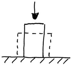
Fig. 14.1
Vertebral plateau
Vagueness exists over the load sharing between the endplate and the cancellous bone underneath. According to White and Panjabi [4] the endplate may contribute 45–75 %. An own rough estimate may yield as follows: The compression strength of a cervical vertebra is in the range of 1585 N [4]. Assuming an endplate surface of 291 mm2 (inferior endplate average of [5]) multiplied with the cancellous bone strength of 2.37 N/mm2 [6] yields on overall strength of 690 N, thus leaving an endplate contribution of 56 %. This becomes important whenever the endplate is resected or damaged in order to accommodate a disc prosthesis or a cage.
Natural Vertebral Disc
The characteristic of the vertebral disc is the compressibility and extendibility of the annulus fibrosus due to the diagonal arrangement of its fibers. Consequently the annulus fibrosus is capable to transfer rotational loads while allowing lateral bending as well as flexion and extension movements. Simultaneously it acts as the seal of the nucleus pulposus providing uniform pressure at arbitrary inclination angles (Fig. 14.2).
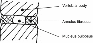

Fig. 14.2
Vertebral disc
Surgical Treatments
Whenever a natural discs has undergone severe degeneration with loss of normal performance it will normally be removed partially or entirely. As replacement two procedures are generally used. One procedure intends to preserve motion whereas the other procedure intends to achieve the fusion with the adjacent vertebrae [7, 8].
(a)
Implantation of a prosthetic disc
Two types of disc prostheses are distinguished. Disc prostheses which move along a geometrical hard sliding core (Fig. 14.3) and disc prostheses which move as a result of the elasticity of an elastomeric core (Fig. 14.4).
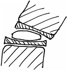
Fig. 14.3
Prosthetic disc with sliding core
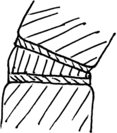
Fig. 14.4
Prosthetic disc with elastomer core
(b)
Fusion of the segment
The fusion of two adjacent vertebral bodies is often assisted by the insertion of a body to maintain height. Such body can be autologous bone, a cage or a combination of both (Fig. 14.5).
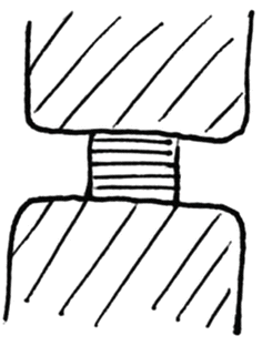
Fig. 14.5
Intersomatic body
Great care must be given to the load transfer from the implant to the vertebra. As soon as the natural endplate is resected or otherwise damaged, the maximum loading capacity may be reduced up to its half. The implant, whether it is a disc prosthesis or a cage, should cover as much surface of the vertebra as possible. If the contact area would be lower, strong bone adherence with consecutive bone remodeling [9] would be required.
Prosthetic Discs
Prosthetic discs are to be divided into two different concepts.
The first concept includes prosthetic discs with a sliding core (Fig. 14.3) (also called “ball and socket”) mostly made of UHMWPE (ultra high molecular weight polyethylene) and two endplates made of titanium alloy. One endplate is sliding over the other imposing an ICR (instantaneous center of rotation) when the adjacent vertebrae undergoes flexion and extension movements. This ICR is often far from the natural ICR. This concept is further subject to wear of the polyethylene core against the metal endplates. This concept does not provide axial elasticity along the vertebral column axis, since the sliding core is too stiff, in comparison with the natural intervertebral disc.
The second concept includes prosthetic discs with an elastomeric core (Fig. 14.4) (also called “silent bloc”). The materials used shall mimic a vertebral disc and have therefore a pronounced elasticity. The mostly used material is the PCU (polycarbonateurethane) (e.g. Bionate ®) possibly blended with silicone (e.g. Carbosil ®). The elastomer core does not impose any cinematic constraints. It allows motion according to it’s elasticity in the specific loading axis. The elastomer core is able to absorb axial loads and to provide axial elasticity along the vertebral column axis.
Cages
A basic feature of an implant material is the stiffness and a basic characteristic of the stiffness is the elastic modulus (also called Young’s modulus ) (denoted as E). But when comparing stiffness from one body to another, the modulus of elasticity is only half of the truth. For comparing stiffness, beside the material constant, also a geometrical parameter needs to be considered, which depends on the type of loading. For axial load (Fig. 14.6) the geometrical parameter is the cross section area (denoted as A) and for bending (Fig. 14.7) the geometrical parameter is the cross section area moment of inertia (denoted as I). Consequently the axial stiffness is given by E·A and the bending stiffness is given by E·I.
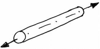
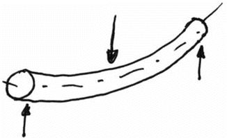

Fig. 14.6
Axial load

Fig. 14.7
Bending load
If in the axial direction the body has a constant cross section (i.e. prismatic) and if the area of contact on the supporting structure corresponds to the cross section, then the area may be dropped from the equation. In all other cases, the areal parameters need to be taken into consideration.
Typical materials used for cages are PEEK (polyetherehterketone), Titanium, carbon fiber composites, PMMA (polymethylmetacrylate) and TCP (tricalciumphosphate) as a filler material.
The cage typically has a frontal contact with the bone and is subject to compression loads. As a consequence the cage is principally exposed to lateral strain (Fig. 14.8), which in the worst circumstances may produce micromotion against the bone, if the interface shear characteristics do not comply with each other. Furthermore, the vertebral endplate would only be loaded on a limited surface, where the endplate itself is being surrounded by compact bone along its periphery; both limiting lateral strain.
