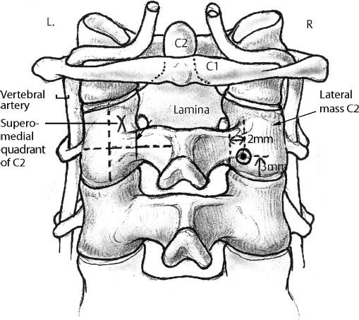
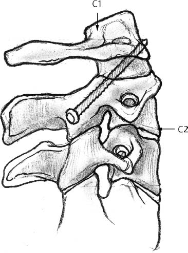
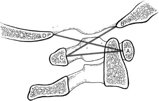
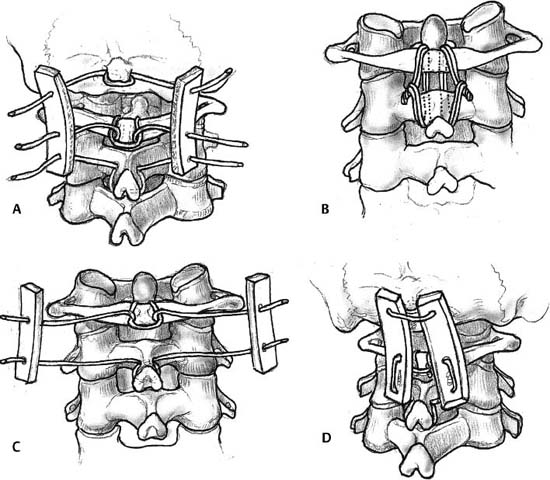
4 I. General considerations A. Functional spinal unit 1. Intervertebral disk 2. Adjacent vertebral bodies 3. Facet joint complex B. Spinal stability 1. Under physiological loading, there is neither abnormal strain nor excessive motion in the functional spinal unit in which neurological structures are protected. 2. Maintained by muscular tension, abdominal and thoracic pressures, and rib cage support in addition to the function spinal unit C. Sagittal balance 1. Maintained by cervical lordosis, thoracic kyphosis, lumbar lordosis, and sacral kyphosis 2. Weight–bearing axis crosses C1, C7, T10, and S2. II. Kinematics A. Cervical spine 1. Occipitoatlantal joint (occiput–C1) a. Thirteen degrees flexion/extension (1) Head nod b. Eight degrees lateral bending c. Four degrees axial rotation d. Coupled motion (1) Occipitoatlantal extension with chin out maneuver 2. Atlantoaxial joint (C1–C2) a. About 45 degrees axial rotation b. Ten degrees flexion/extension c. No lateral flexion a. Flexion/extension (1) Greater mobility in the sagittal plane is due to the orientation of the facet joints in 45–degree horizontal plane. (a) C2–C3 (8 degrees) (b) C3–C4 (13 degrees) (c) C4–C5 (12 degrees) (d) C5–C6 (17 degrees) (e) C6–C7 (16 degrees) (f) C7–T1 (9 degrees) b. Lateral bending (1) Sixty degrees coupled with rotation (a) Spinous process is rotated toward the convexity. c. Axial rotation (1) Fifty percent of rotation takes place in the subaxial cervical spine. B. Thoracic spine 1. The ribs and steep orientation of the facets limit range of motion (ROM). a. Flexion/extension (1) Seventy–five degrees combined sagittal motion (2) Flexion is greater than extension. (3) Flexion increases caudally. b. Axial rotation (1) Seventy degrees axial rotation (2) Rotation decreases caudally. c. Lateral bending (1) Seventy degrees lateral bending 2. More flexion/extension and lateral bending motion is present in the lower vertebral segments, but rotation is less. 3. Some degree of rotation accompanies lateral bending. a. Spinous process rotates toward the convexity in the upper thoracic region. b. In the middle to lower thoracic region, the direction of coupling is not consistent. C. Lumbar spine 1. Flexion/extension a. Eighty–five degrees combined flexion/extension ROM b. Flexion is greater than extension. c. Motion is greater caudally. 2. Lateral bending a. Thirty degrees ROM 3. Axial rotation a. Sagittal orientation of the facets limits rotation. b. Rotation is least at L5–S1. III. Biomechanics of spinal instability and instrumentation A. Occiput–cervical spine 1. Occiput–C1 instability a. Distance from the tip of the dens to basion of the occiput (1) Normal is 4 to 5 mm. (2) Greater than 1 mm translation on flexion–extension is abnormal. (3) Power’s ratio is used to determine anterior atlanto–occipital dislocation (Fig. 4–1). (a) Distance between the basion and the spinolaminar line of C1 divided by the distance between the posterior margin of the foramen magnum (opisthion) and the posterior margin of the anterior arch of C1 (i) A ratio >1 signifies anterior atlanto–occipital instability. 2. Basilar invagination a. McGregor’s line (1) Greater than 4.5 mm odontoid projection above the foramen magnum b. Ranawat’s C1–C2 index (1) Less than 13 mm is abnormal. c. Redlund–Johnell O–C2 index (1) Abnormal distance (a) Less than 33 mm (men) (b) Less than 27 mm (women) 3. Atlantoaxial (C1–C2) instability a. Transverse ligament is essential for stability (1) Atlantodens interval (ADI) (a) ADI > 3 mm indicates rupture of the transverse ligament. (b) Greater than 5 mm of ADI indicates rupture of the transverse and alar ligament. (c) Greater than 4.5 mm is abnormal in children. (2) Space available for the cord (SAC) (a) Greater than 10 mm of ADI or SAC <14 mm impinges on the spinal cord. b. Atlas fractures with > 6.9 mm lateral displacement indicates rupture of the transverse ligament. 4. C2 fractures a. Odontoid fractures produce C1–C2 instability. b. C2 pedicle or the Hangman’s fracture (traumatic spondylolisthesis of C2) (1) Unstable in flexion B. Fixation of the upper cervical spine 1. Posterior methods a. Sublaminar wiring (1) Gallie wiring is weaker than Brooks technique. (a) Particularly in rotatory and anterior translatory motions (Fig. 4–2) b. Transarticular screw technique (Magerl) (1) Stronger fixation especially in rotation (Fig. 4–3) c. Occipitocervical plates or Luque rods are stronger than wires. d. C1 lateral mass screw/C2 pedicle screw (Figs. 4–4, 4–5) (1) Strongest biomechanical fixation 2. Anterior odontoid screws (Fig. 4–6) a. Biomechanically stronger with two screws (1) One screw may be adequate clinically. C. Biomechanics of the lower cervical spine 1. White and Panjabi checklist for clinical instability a. Anatomic components (1) Anterior stability (a) Anulus fibrosus (b) Anterior longitudinal ligament (c) Vertebral body (2) Posterior stability (a) Posterior longitudinal ligament (b) Facet joint and capsules (c) Lamina and interspinous ligaments b. Clinical checklist (1) A total of 5 points or more is considered unstable. (a) Disruption of anterior elements: 2 (b) Disruption of posterior elements: 2 (c) Relative sagittal plane translation greater than 3.5 mm: 2 (d) Relative sagittal plane rotation greater than 11 degrees: 2 (e) Positive stretch test: 2 (f) Cord damage: 2 (g) Root damage: 1 (h) Abnormal disk narrowing: 1 (i) Dangerous loading anticipated: 1 2. Ligamentous disruption of >3.5 mm or 11 degrees indicates instability.
Biomechanics of the Spine and Spinal Instrumentation
Neupsy Key
Fastest Neupsy Insight Engine