Fig. 4.1
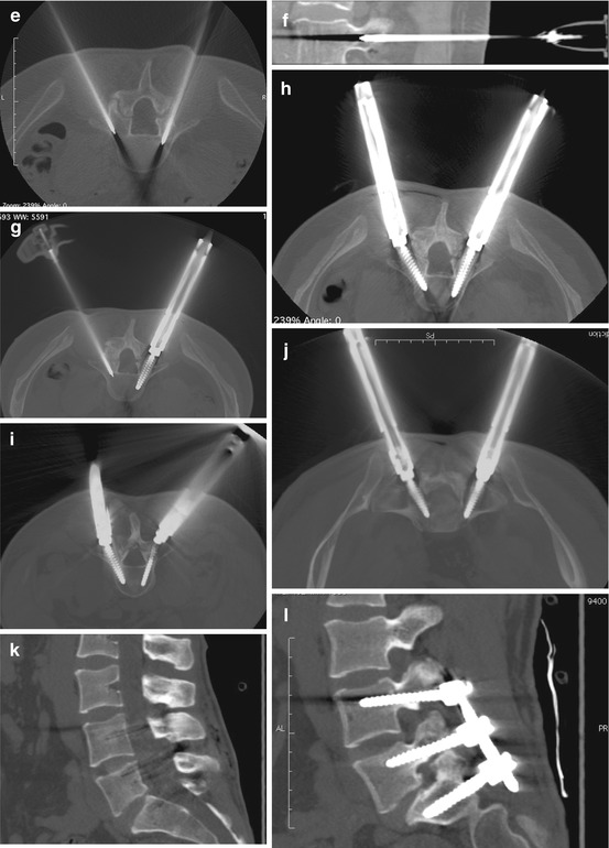
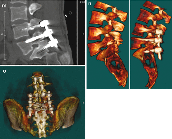
L4–S1 posterior fixation (PIF) in a patient affected by L5 spondylolisthesis and bilateral peduncular spondylolysis, with bilateral severe L5 sciatica and mild lower limb paresis. Preoperative 2D CT scan recon image at the midline (a) and at the level of right (b) and left (c) L5–S1 foramina. A mild (grade I) anterolisthesis of L5 can be appreciated on the midsagittal image: L5 nerves are compressed due to severe bilateral foramina stenosis at the level of L5/S1. A couple of 20G Chiba needle for each level to be treated is placed directly through the chosen route to the pedicle area, and lidocaine is injected for local anesthesia (d). An 11G Jamshidi needle is introduced pointing to the pedicle, and the needle advances into the pedicle depth, till the posterior third of the vertebral body is reached (e). Real-time in vivo 2D recon along the needle axis is always useful in demonstrating correct needle position, preventing neural or vascular damage related to malposition (f). On the right side, a 35 mm length screw is introduced into the outer dilatator penetrating the right pedicle till the posterior third of the vertebral body is reached (g). Then the procedure is repeated on the contralateral side, introducing a Jamshidi needle into the left L5 pedicle (g), and a second screw is precisely introduced into the pedicle: thanks to CT guide, the screws are always centered into the pedicle even in asymmetrical pedicle position (h). After screw positioning, intra-peduncular screw into the L4 pedicles (i) and into the sacrum via the S1 pedicle (j) are introduced with the same technique. The CT control scan clearly depicts the correct position of the screw, avoiding accidental nerve or vascular injury, as well as sacral foramina involvement (j). On postoperative L4–S1 posterior fixation (PIF) 2D CT scan recon image at the midline (k) and at the level of right (l) and left (m) L5–S1 foramina, reduction of L5 spondylolisthesis, with regular position of the fifth lumbar vertebra, can be appreciated. Thanks to reduction-distraction forces applied, the L5/S1 neural foramina are widened (l, m), as compared to preoperative 2D sagittal recon images (b, c). 3D sagittal scan at the level of the left L5/S1 foramen (n) before (left) and after (right) reduction of L5 and distraction of L5/S1 space is useful in demonstrating the obtained widening of the left L5/S1 foramen, showing almost normal round shape on postoperative image. Finally, the correct position of the two bars from L4 to S1 can be easily appreciated on 3D image (o)
As for other more widespread CT procedures like vertebroplasty, once the entry level point is chosen on CT image, no skin landmarks are needed, as conventional CT gantry laser light is used to target the right orientation of tools.
A 20G Chiba needle is placed directly through the chosen route to the pedicle and 5–7 cc of lidocaine is injected for local anesthesia (Fig. 4.1d), while the patient undergoes simple analgo-sedation (fentanyl 1–3 gamma/kg/h/remifentanil 0.2–0.3 gamma/kg/h), to reduce pain sensation.
Conventional 11G Jamshidi needle is introduced along the same route, and after initial cortical pedicle perforation, the needle is advanced into the pedicle depth, reaching the posterior third of the vertebral body (Fig. 4.1e–f). Then the inner trocar of the Jamshidi needle is pulled out, and a 20 cm K-wire is inserted into the cannula. The cannula is pulled out, maintaining the probe firmly inserted into the pedicle: caution in probe advancing is necessary to avoid accidental advancement of the K-wire. Then, the outer shaft of the Jamshidi needle is removed, and coaxial soft tissue dilators are introduced twisting clockwise to allow gentle muscles and soft tissues spreading. The dilators reach the pedicle cortex, confirming it using C-arm fluoroscopy, and all the inner smaller dilators are removed, but the external larger one, remaining as a working cannula.
Despite tapping the pedicle with specific tools to enlarge the pedicle access is adopted by several authors, new self-tapping titanium pedicle screws do not necessary need this additional procedure step. A pedicle reamer is introduced on the pedicle probe, and reamer manual rotating is performed, removing the interfering bone for each pedicle. The screw is inserted through the outer dilator into the pedicle, and the process is repeated for the contralateral pedicle (Fig. 4.1g, h), and next to the other pedicles according to the levels to be treated (Fig. 4.1i, j).
As the screws are tightened, if reduction of spondylolisthesis has to be performed, distraction forceps are applied gently to reduce the listhesis. The appropriate length of titanium rods is selected using a rod bender, and rods are applied directly through the cannula at lower level, moving towards the upper screw one. A rod pusher is used to fix the rods to screws. Finally, locking caps to screws are attached; all the devices are removed and skin suture follows (Fig. 4.1k–o).
4.2 Posterior Facet Fusion (FF)
One of the most common causes of low back pain (LBP) is the well-known lumbar facet chronic arthritis, generally related to disc degeneration, the disc loosing the capacity to absorb mechanical load stress, pushing the overload to the posterior arches element [29]. Because of acquired facet joint asymmetrical load and distress, progressive articular cartilage degeneration and bone remodeling occurs, causing chronic LBP (chronic facet joint syndrome – CFJS). The CFJS is the main cause of LBP in young patients, particularly in those undergoing local extra-stress (sport activity, overweight). As a chronic syndrome, conventional drug therapy (steroid infiltration, analgesics) only has temporary effect, the pain being related to a mechanical cause more than a simple local inflammation.
Zygapophysial nerve radiofrequency ablation (RF) is the widespread frontline treatment for the CFJS, resolving or reducing the LBP in most of the patients [30]: however, RF failure, that is, persistent LBP till 2 months after the treatment, frequently related to incomplete nerve radioablation (determined by wide anatomical variability), occurs in 21 % of cases [31]. Moreover, a significant increase in failure percentage is observed in patients who have previously undergone posterior laminectomy (59 % of failure) or posterior interbody fusion (71 %) [32, 33].
Despite PIF has been adopted by several authors, it seems to be an aggressive technique (perineural scars, extensive muscle dissection leading to muscle dysfunction) to be adopted in patients with a simple CFJS [34]. Moreover, increasing rigidity of a spinal unit after implant can lead to overload stress transmitted to contiguous functional spinal unit (FSU), accelerating disc degeneration/herniation, as well as painful subchondral bone edema related to stress shearing impact [35, 36]. Lateral interbody fusion (LIF) can be safely performed reaching equivalent biomechanical stability of stand-alone cage placement compared to posterior fixation obtained with PIF technique [37]: nevertheless, LIF implants need general anesthesia as well as extensive deep paraspinal muscles dissection, with muscle dysfunction similar to PIF fusion, increasing general spine instability.
Recently, new percutaneous approaches have been proposed to perform posterior facet joint fixation (PFJF). As for several different fixation system like interspinous fasteners [38], PFJF was demonstrated to obtain near equivalent immediate stabilization of the lumbar spine, as for LIF or PIF [39]: on several biomechanics tests, PFJF was as stiff as other procedure when compared to lateral bending, cyclic flexion/extension, and torsion of the lumbar. Moreover, anterior column loading on in vitro compression tests showed no biomechanical differences in comparison to more aggressive stabilization. For this reason, posterior facet fusion is gaining popularity even for posterior stabilization after anterior lumbar interbody fusion [40]. As degenerative spondylolisthesis is very common in elderly patients affected by osteoporosis, the rate of failure of conventional pedicle screws fixation is high, leading to pseudoarthrosis, potentially requiring new surgery: for this reason PFJF has been adopted as a valid alternative in case of spinal instability in patients affected by severe osteoporotic disease [41].
The PFJF results as a very quick one-step procedure under simple local anesthesia and/or mild sedation, significantly reducing the total working time [42], preserving muscle anatomy (no deep dissection is needed), and the adjacent facet joint [43].
Lumbar PFJF can be performed on a simple C-arm, using the inferior endplate and medial pedicle wall of the superiorly instrumented level as anatomic landmarks in conjunction with axial and sagittal angles of insertion [40, 44]. However, in case of joint and/or pedicle bone deformation related to axial instability, lateral and anterior-posterior X-ray view is frequently unsafe because of incorrect visualization of conventional pedicle landmarks. Performing the procedure under a combination of C-arm and CT control results in better choice of the correct size, length, and orientation of fixation tools like trans-articular screws or intra-articular implants, avoiding extravertebral or extra-articular incorrect fixation placement, as well as soft tissue or vascular damages [5].
The most used and popular posterior PFJF is based on trans-articular screw fixation (TFF). The TFF is an easy to perform procedure, allowing excellent joint fixation, resolving LBP (Figs. 4.2, 4.3, and 4.4). A limitation of the procedure based on screws introduction can be the difficulty in drilling excessive sclerotic pedicle bone, particularly in elderly patients with long-standing chronic deforming arthritis and in patients affected by bone weakness related to severe osteoporotic disease. In these patients (Fig. 4.5), different kinds of facet fusion can be adopted. Recently, very minimal invasive intra-articular implants (intra-articular facet fixation – IFF) has been used in patients with LBP related to CFJS, with contraindication to trans-facet fixation. Intra-articular fixation, thanks to the gentle introduction of intra-articular implant fixed with micro-screws, is definitely the less invasive fusion technique concerning the joint bone architecture. Moreover intra-articular implants can be proposed even for cervical spine, while TFF screws do not fit well in this area [41, 45, 46, 47]. On the other hands, IFF should be used when straight intra-articular rim occurs only, being difficult or impossible to introduce the implant in case of severe joint deformation related to bone remodeling as a result of asymmetrical load and/or arthrosis (Fig. 4.6). Despite bone removal pliers can be adopted to remove osteophytes, articular process weakening should always be avoided to maintain the joint as stable as possible for implant insertion. In these cases, TFF with trans-articular screws should be preferred to IFF. Recently, new totally plastic devices has been proposed, that can be fixed into the articular space without the use of any screw, and anchored into the space thanks to a PEEK surface fully covered with small hooks (Fig. 4.7 ).
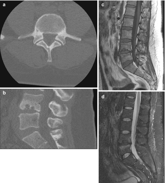
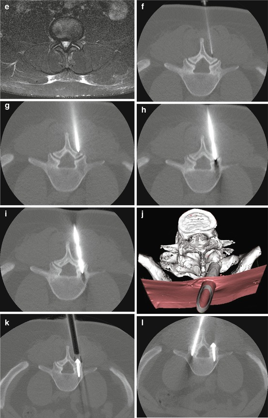
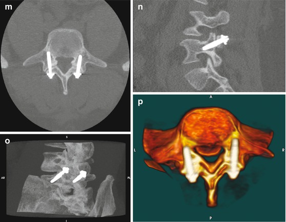
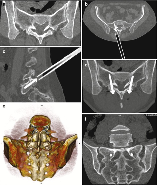


Fig. 4.2
L4/L5 instability related to local disc degeneration and related painful facet joint syndrome in a 32-year-old man (professional biker). Despite apparently normal L4/L5 facet, with regular cortical thickness and articular rim orientation on axial CT image (a), local instability is suggested by severe disc degeneration responsible for subchondral bone sclerotic reaction on sagittal 2D CT recon image (b). On sagittal SE T1-weighted (c) and STIR T2- weighted (d) MR images, evident signal intensity reduction of L4/L5 disc, as well as local subchondral edema, is appreciated. Axial STIR T2-weighted image of articular joints clearly depicts bilateral bright signal intensity inside the articular rim, an indirect sign of local microinstability (e). A 20G spinal needle is advanced through the paravertebral soft tissues, pointing to the inferior articular process of L4 and 3–5 cc of local anesthetic drug is injected (f). After that, 11G Jamshidi needle is introduced along the Chiba needle trajectory, targeting to L4 medial inferior portion of the inferior articulating process (g). The tip of the needle advances through the articular rim (h), overpassing the articular rim and penetrating into the superior articular process of L5 for approximately 10–15 mm (i). Fast 2D (j) and 3D (k) CT image reconstruction allows correct position of trans-articular screw through muscle dilator. After having performed right side TFF, contralateral procedure starts, by introducing symmetric contralateral Jamshidi needle (l). 2D CT axial (m) and sagittal (n) images at the level of the left articular process and 3D MIP (o) and surface rendering (p) postoperative controls show the correct screw position, excluding eventual complications. 3D images clearly shows screw position into the articular space

Fig. 4.3


L5/S1 level facet joint syndrome in a 54-year-old female affected by local disc disease. On axial CT scan, mild sclerotic reaction at the level of articular subchondral bone can be appreciated (a), with asymmetrical widening of the left articular rim and narrowing of the contralateral one. L5/S1 trans-facet screw is introduced via muscle dilator through inferior articular process of L5 and superior articular process of S1 (b, c). 2D (d) and 3D (e) image clearly shows the correct route of the screws, as well as the position of screws cap (e). For optimal biomechanical fixation screws remain as parallel as possible, accidental sacral foramina involvement being avoided thanks to continuous CT control during the procedure (f) (c, d Courtesy of Interventional Neuroradiology)
Stay updated, free articles. Join our Telegram channel

Full access? Get Clinical Tree


