Fig. 7.1
Axial CT scan (bone window) in a patient with bilateral sacroiliac joint degeneration. CT image clearly depicts indirect sign of sacroiliac instability and degeneration, with intra-articular gas related to cartilage degenerative disease and joint sclerotic rims, as well as diffuse subchondral sclerosis of the bone
As for other acute and chronic joint inflammation, MRI allows more accurate diagnosis of SIJ inflammatory disease, particularly using short-time T2-weighted inversion recovery sequences (STIR), as well as fat-suppressed contrast-enhanced T1-weighted scans; STIR images demonstrate the typical high signal intensity symmetrical band frequently at both sides (iliac and sacral) of the SIJ (Fig. 7.2), and evident contrast enhancement of the subchondral bone is detected on T1-weighted images after contrast injection (Fig. 7.3). However, as a rule, not all the SIJI are characterized by inflammatory reaction, particularly in the acute phase. Moreover, there are several papers demonstrating age-related increased abnormal MRI findings at the lumbar area and SIJ that occur in asymptomatic patients [50, 51]. As a result, MRI findings lack specificity and cannot prove without doubt correct correlation between pain and signal abnormality (Fig. 7.4b).
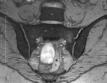
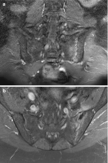
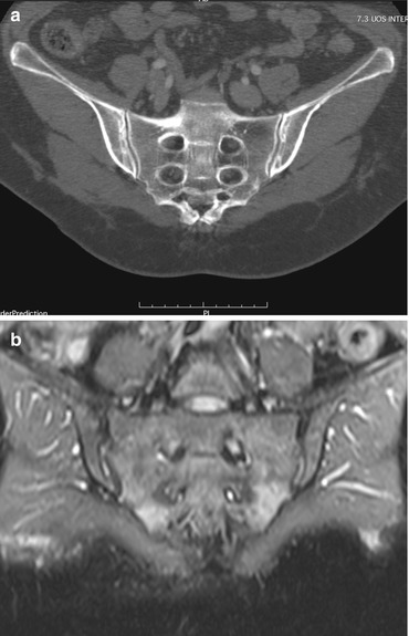

Fig. 7.2
Coronal T2-weighted short-time inversion recovery (STIR) scan in a patient affected by left SIJ pain. On coronal scan, faint high signal intensity of the subchondral bone at the level of the left sacral wing can be appreciated, related to local sacroiliac disease. Bright signal intensity inside the superior third of the articular space can be related to local inflammation and/or excessive intra-articular fluid, as usual in the case of chronic instable joint. Note the irregular SIJ rim, secondary to chronic articular degeneration

Fig. 7.3
Fat-suppressed contrast-enhanced coronal (a) and axial (b) MR scans at the level of the sacroiliac joints in a patient affected by left SIJ pain and instability. Contrast-enhanced CT scans clearly depict pathological enhancement at the level of the left intra-articular sacroiliac space and the subchondral bone on both the iliac and sacral sides of the joint

Fig. 7.4
Patient affected by bilateral SIJI. 2D coronal CT recon image (a) and T2-weighted STIR image (b). On CT scan, a subtle double sclerotic rim on the iliac side of SIJ suggests the disease, while on MRI scan, only mild high signal intensity of the lower sacral wings, far away from the SIJ rim, cannot be considered specific for the correct diagnosis
Bone scanning, and subsequent SPECT (single-photon emission computed tomography), is a very sensitive technique in demonstrating sacroiliac joint inflammation as an area of active radionuclide uptake inside and around the articular rim, but this diagnostic tool suffers from very low specificity and the patient is exposed to radiation effects. Moreover, bone scanning showed very poor sensitivity (14–46 %) in chronic SIJI without severe inflammatory reaction [52, 53], and Maigne concludes “no additional value regarding the diagnosis of a sacroiliac syndrome” [54].
Single or double diagnostic block of the SIJ using lidocaine intra-articular injection is considered the gold standard in pain related to SIJI demonstration, preferably on a CT-guided technique [55, 56]; when lidocaine is to be injected, one should be careful to introduce the small 20–22-G Chiba needle preferably into the upper one-third of the sacroiliac joint, this area being the most innervated part of the joint. If correctly performed, lidocaine block is considered the most reliable test [57], certifying the SIJ to be the pain generator responsible for the clinical symptoms of the patient.
When treatments are considered for patients affected by painful SIJI, radiofrequency ablation (RFA) of the sacroiliac rim is generally proposed. However, although radiofrequency ablation is considered a safe procedure without major side effects as described in the literature, the efficacy of RFA does not exceed 64 % of the cases [58]. One of the causes of relative frequent failure of SIJ RFA is related to the fact that RF treatment can destroy posterior SIJ innervation only, being impossible to act against the anterior nerves framework that concurs to pain generation [6].
When RFA failure occurs, SIJ arthrodesis should be taken into account in patients suffering the disease with disabling symptoms.
In the past, several techniques have been proposed such as conventional “open” surgery in an attempt to stabilize the SIJ, obtaining sacroiliac arthrodesis using different tools [59]; anterior fusion generally is performed after sharp dissection of the gluteal fascia and external oblique muscles, with subsequent removal of the superior capsule and the cartilage of the SIJ; after that, bone cancellous screws and bone graft in predrilled holes through the joint are introduced [60]. Lateral open SIJ fusion according to Smith-Petersen technique as well as anterior or posterior intra-iliac approach has been proposed also [60].
Recently, however, new percutaneous systems (“covert surgery”) have been proposed to obtain a fast one-step articular fusion. Several functional tests performed on cats’ and sheep’ SIJ [61], consisting of the evaluation of anatomic variation on pre-op C-arm radioscopy, introduction of three Steinman pins along the direction desired, and implantation of triangular-shaped titanium implants using a coaxial cannulated system, revealed as a powerful technique in SIJ stabilization, with no need to underwent open surgery anymore [62].
One of the main advantages of these new fully CT- and X-ray-assisted covert surgery techniques is the possibility to avoid general anesthesia for the patients, as simple analgo-sedation combined with local lidocaine injection is sufficient.
Another advantage of this technique is the unilateral approach; as several studies demonstrated, a single unilateral fusion is sufficient to stabilize the SIJ [60]; consequently, the patient undergoes one single unilateral treatment, generally performed on the more painful side.
Moreover, because of the porous nature of the implants (titanium plasma coating) and a specific design, spontaneous cancellous bone regrowth occurs in the 3rd to 6th week after implant introduction, making other procedures such as bone tamp or iliac crest bone harvesting not to be required.
Minimally invasive SIJ fusion with unilateral approach and C-arm fluoroscopy has been used resulting in good stabilization and pain resolution. However, simple X-ray-guided technique can be affected by several drawbacks, the most important being the great anatomical variability of SIJ morphology, with the risk of incorrect placement of implants and consequent treatment failure.
As for other minimally invasive techniques like vertebroplasty or percutaneous spacers, CT-guided techniques dramatically reduce the complication rate of percutaneous procedures [63]. Moreover, performing SIJ fusion under CT control dramatically reduces exposure to radiations and potential risks for patients and physicians. The radiation dose absorbed by the patient in conventional spine surgery assisted by 2D fluoroscopy is more than fivefold greater than in CT-guided technique in the case of SIJ fusion. As a result, when compared with conventional fluoroscopy, “the patient’s effective dose can be reduced by 3D computer-assisted spinal and pelvic surgery” [64].
Despite recently proposed 3D intraoperative fluoroscopy has been suggested as a powerful tool in iliosacral screw implant, allowing fast detection of screw misplacement more reliably than conventional 2D fluoroscopy [65], the winning key still remains screw insertion in the best position at the very first try, an easy goal obtained with CT-guided technique.
Pre-op and in vivo CT study during the procedure is mandatory for an accurate planning of the joint area to be treated, as well as the optimal choice of implant size, while immediately post-op CT scanning allows early evaluation of possible local side effects like hemorrhages. As an equidistant position of the implants covering the area of the superior one-third of the SIJ is fundamental to assure a stable fusion, images of the SIJ surface area on CT real-time 2D recon allows to best evaluate the right place to insert the implants. Moreover, CT allows calculating precisely the maximal length to be adopted for each specific case. This is a key point according to several biomechanical studies, demonstrating the SIJ stabilization obtained with implants increases proportionally to the length; as the mean SIJ area in adults is 1,600 mm2, a total coverage of the area is offered using three titanium implants, calculating that the stabilized area covered is approximately 1,000, 1,400, and 1,800 mm2 when a 35, 45, or 55-mm implant is selected [66].
7.1 CT + X-Ray-Guided Sacroiliac Joint Fusion Technique
Using a CT-guided technique and analgo-sedation, with simultaneous X-ray control, thanks to a C-arm placed over the CT table, the patient is positioned prone. As a lateral approach is adopted, the access usually occurs at the side of more evident SIJ pain.
A previous pre-op CT scan is performed, and the level to be treated is chosen, according to the morphology of the area to be treated, and local injection of 10 cc of lidocaine is performed using a simple 20-G spinal needle (Fig. 7.5).
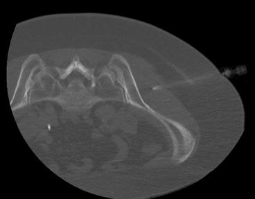

Fig. 7.5
SIJ fusion. The patient lying in prone position on the CT table, a small 20-G Chiba needle is placed along the chosen route for the implant insertion, and 5–10 cc of local anesthetic is injected
Then, a 17-G Jamshidi needle is advanced through the superior third of the selected SIJ, and the iliac bone is penetrated for 15–20 mm approximately (Fig. 7.6). The internal needle is pulled out and K-wire is introduced.
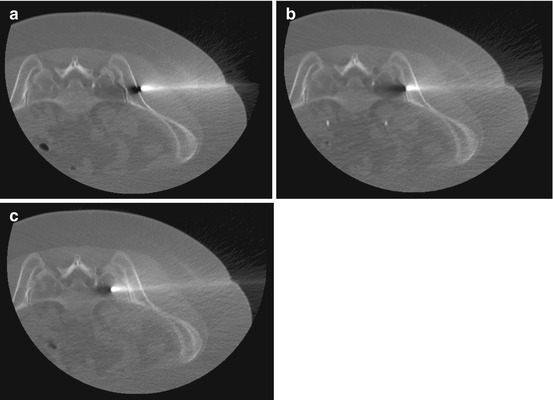

Fig. 7.6
After Chiba needle removal, a 17-G Jamshidi needle is advanced pointing to the superior third of the selected SIJ advancing into the iliac bone (a), reaching the SIJ space (b), finally introduced 15–20 mm into the sacral wing (c)
After cutting the skin around the guidewire for approximately 10 mm, coaxial soft tissue dilators are introduced (Fig. 7.7). As the drill sleeve and pin sleeve together come in contact with the sacral bone (Fig. 7.8a), the pin sleeve is removed, and a manual driller is introduced over the guidewire, to drill the sacroiliac bone, creating a cavity. Care should be taken in remaining approximately 15 mm far from the first sacral foramina; for this reason, drilling is continuously monitored via X-ray C-arm control on AP view. By removing the drill handle and maintaining the drill firmly attached into the sacral bone, a fast CT control to avoid incorrect placement and to perform in vivo measurement from the driller to the sacral foramina can be performed (Fig. 7.8b).
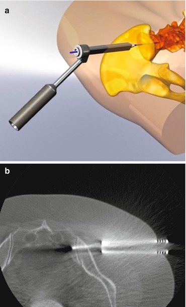
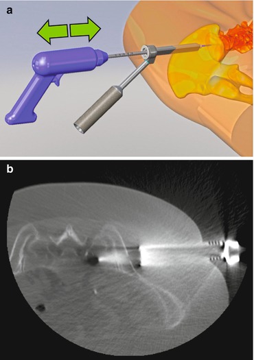

Fig. 7.7
Progressive dilators are introduced over the K-wire (a). Then all the dilators but the external largest are removed, maintaining the K-wire firmly introduced into the sacral bone (b)

Fig. 7.8
Using the K-wire as a safe driver, the manual driller is introduced coming in contact with the sacral bone (a), drilling a cavity for the future implant; care should be taken in remaining approximately 15 mm far from the first sacral foramina, as one can precisely control even on fast CT scan images (b)
The drill sleeve is removed, and tapping is performed through the created hole, to enlarge the bony access (Fig. 7.9). The broach is smaller than the implant (15 mm smaller), the way the implant can be firmly pushed into the bone.
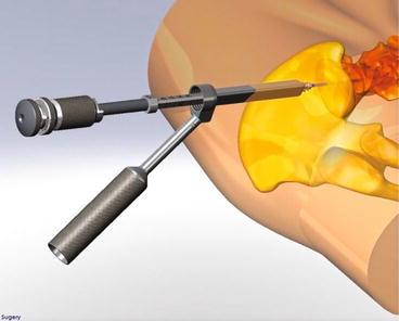

Fig. 7.9
As the implant needs a much larger hole than the one obtained with simple drilling, tapping is performed through the pre-created hole, to enlarge the bony access; the tapper is generally 2–3 mm smaller than the implant, to obtain future firm insertion of the implant
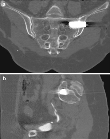
Real-time 2D measurement offers the possibility to choose the correct length of the implant (generally ranging from 25 to 50 mm); implants can have different size and shape, obtaining maximal porotic surface exposure to the local bone, increasing new bone regrowth into the implant (Fig. 7.10a, b). Once the correct implant is chosen, the operator places the implant over the pin, finally introducing it into the preformed sacroiliac hole (Figs. 7.10c and 7.11a). Then the K-wire is removed, the implant remaining as a bridge passing through the SIJ (Fig. 7.11b). The correct position of the implant is ruled out with post-op CT scan (Fig. 7.12).
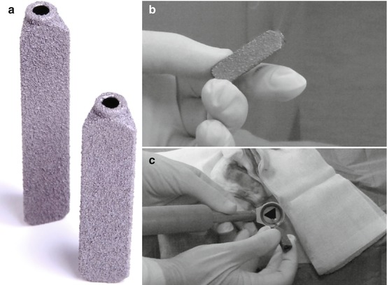
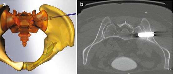

Fig. 7.10
Introducing the implant. The SIJ implant (generally ranging from 25 to 50 mm) can have different size and shape, maximizing the surface exposure to the sacral and iliac bone, stimulating ingrowth of new bone (a, b). Once the correct implant is chosen, the operator places the implant into the dilator, over the pin (c)

Fig. 7.11
The implant is pushed over the K-wire, finally reaching the preformed sacroiliac cavity (a). Then the K-wire is removed, and the implant remains into the cavity, passing through the SIJ as a metallic bridge (b)
