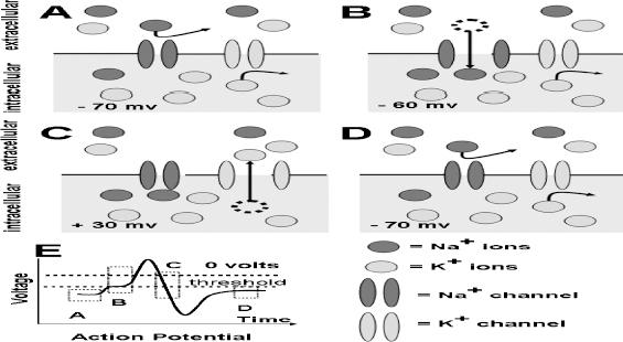
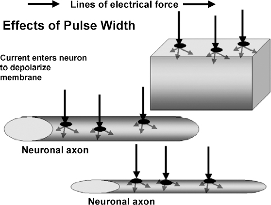
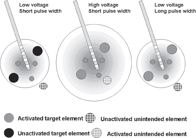
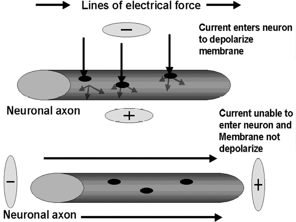
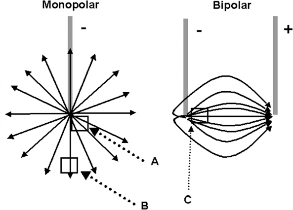
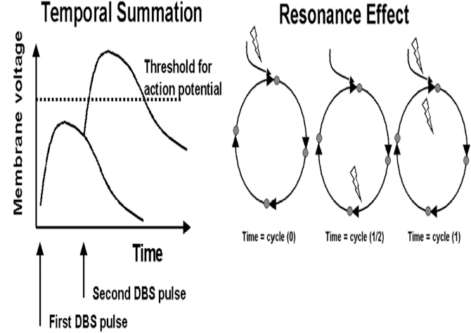
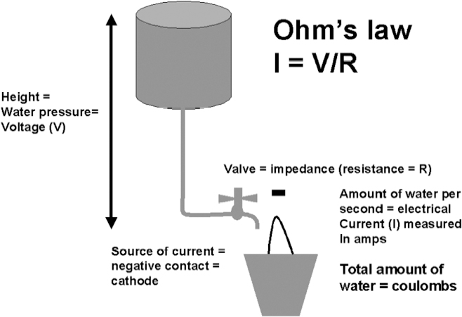
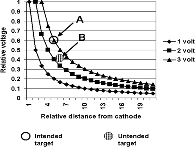
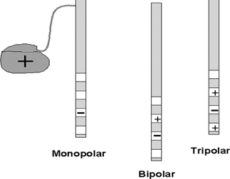
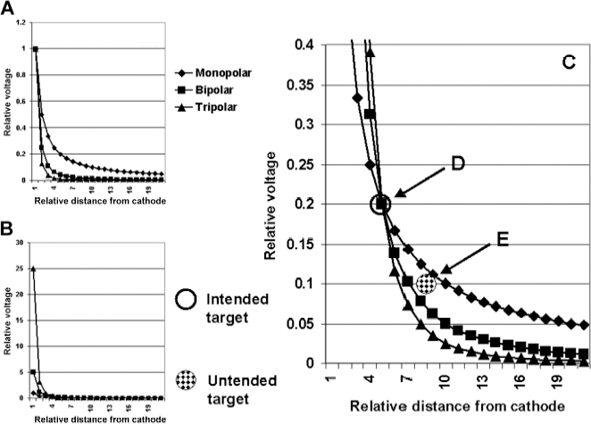
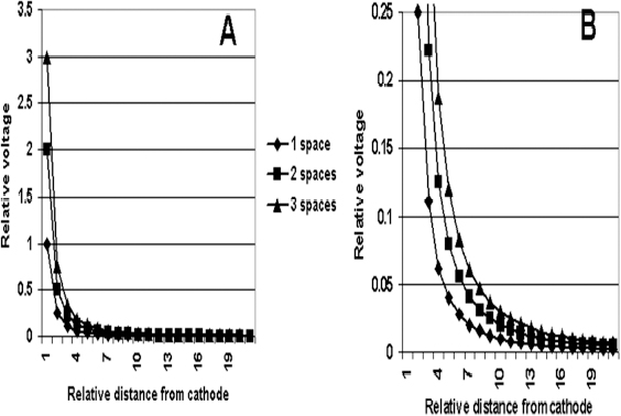
13 Deep Brain Stimulation Programming Erwin B. Montgomery Jr. Deep brain stimulation (DBS) is already standard therapy for several chronic neurological conditions, including Parkinson disease (PD), essential tremor, cerebellar outflow tremor such as that due to multiple sclerosis, and dysto-nia.1–4 Clinical trials are under way or planned for epilepsy, obsessive-compulsive disorder, depression, and minimally conscious state patients. With regard to PD, DBS has helped patients for whom the most aggressive pharmacological interventions1 and fetal cell transplants have failed.5 Yet, despite the remarkable efficacy, fewer than anticipated numbers of patients are being referred for DBS. There are many factors contributing to this underutilization. One of them is the perceived difficulty in managing these patients postoperatively. The central theme of this chapter is that effective postoperative DBS adjustments are not happenstance or the result of random chance. Nor should programming be based solely on historical precedent, which risks perpetuating misconceptions. “Cookbooks” are ineffective given the variability among patients and the over 4000 possible combinations of stimulation parameters (active contacts, voltage, pulse width, and frequency). There are principles that guide DBS management. These principles are based on electrophysiological properties and the regional functional anatomy surrounding the DBS lead. DBS management is primarily science with a little art. As a science, it can be learned by a rational approach that does not depend solely on the experience of the DBS adjuster. A programmer has to decide whether to invent a sufficiently large cookbook with the potential to address the multitude of programming problems, or to invest in learning a handful of principles that can be recombined and tailored to any number of patients. Efficient strategies for DBS programming are important for cost-effective and timely care. An important concept is that the therapeutic benefit of DBS is related to adequate activation of target structures. Factors include the volume of brain stimulated and the number of neuronal elements activated within that volume. Generally, the volume of brain activated is related to the size of the electrical field generated by DBS. The number of neuronal elements within the volume activated is related to the current density, which is the concentration of electrons (ions) within the electrical field. Thus effective activation is a complex interaction of electrical field size and strength and the unique properties of the neuronal elements affected. DBS injects electrical charge into the brain. With metallic conductors, charge is in terms of electrons. In the brain, charge is mediated by ions. To facilitate use of the analogy of DBS to electronics, electrons and ions will be used interchangeably. We can manipulate the size of the electrical field by adjusting the voltage and the combinations of active DBS contacts. We can manipulate the current densities within the electrical field by changing the configuration of the active DBS contacts. For example, monopolar stimulation, where a single contact on the DBS lead acts as the cathode (negative contact) and the impulse generator case acts as the anode (positive contact), generates less concentrated current densities compared with bipolar where the anode and cathode are on the DBS lead. The side effects of DBS are directly related to stimulation of unintended structures. This will depend on the unique regional anatomy of the individual patient and the orientation of that patient’s DBS lead to the regional anatomy. This means that the shape, size, and strength of the electrical field will be critical. We can manipulate the shape, size, and strength of the electrical field by changing the configurations of the active contacts on the DBS lead. There is clear evidence that DBS excites a variety of neuronal elements and that it does not inhibit neuronal activity, at least directly.6,7 We use the term neuronal elements because we do not know which specific elements, such as axon initial segments, internodes, cell bodies, and/or den-drites, mediate the DBS effect. How are neuronal elements excited? Neuronal activation requires generation of an electrical impulse across the cell membrane that is transmitted down the axon to the next neuron.8 Electrical impulses generated are in the form of electrically charged ions that flow across the cell membrane. For electrically charged ions to flow, there must be a force that will move the ions. This force is called the membrane voltage and is the difference between the forces on each side of the membrane. This difference in force across the membrane is generated by pumping sodium (Na+) out of the cell and in exchange moving potassium (K+) ions in. The resulting difference in Na+ and K+ (and other ions as well) creates a chemical concentration difference (gradient) that will tend to move ions, for example, Na+ into the cell and K+ out. When these ions flow across the cell membrane in sufficient quantity, there is an electrical impulse called the action potential (Fig. 13.1). The cell membrane resists the flow of ions and therefore, the generation of an electrical impulse or action potential. However, channels in the cell membrane can open allowing ions to flow across the cell membrane and generate an electrical impulse. One way to open these channels is to change the voltage inside the cell relative to the voltage outside. If the inside of the cell becomes less negative (called depolarization) to a certain threshold, then the channels open and allow the flow of ions and the creation of an electrical impulse or action potential. DBS acts to depolarize the cell membrane, to open the channels and create an electrical impulse (Fig. 13.1). To depolarize the neuronal cell membrane, DBS has to drive electrical current, which is the flow of electrical charges, into the neuron across the cell membrane. The voltage of the DBS pulse is what drives the current into the neuron. Thus, by controlling the voltage we can control which and how many neurons are depolarized to generate action potentials. Also, the longer the duration of the DBS pulse (pulse width) the more current will be driven into the neuron, and there will be greater depolarization and greater probability of generating an axon potential. Thus we can see that already we have two means to control the generation of action potentials, voltage and pulse width. The size and shape of neuronal elements can vary greatly. We can take advantage of this variability to control which neuronal elements are activated by DBS. Smaller-diameter neuronal elements such as axons are excited at lower voltages than large elements such as neuronal cell bodies. However, larger-diameter axons are excited at lower voltages than small-diameter axons. Thus, by controlling the voltage we can control which neuronal elements are activated. Also, the voltage generated in the brain tissue decreases the further the distance from the electrode. By controlling the voltage we can control the volume of tissue that experiences sufficient voltage to generate action potentials. Controlling the pulse width also controls which neuronal elements are activated. Small elements, such as axons, can be activated by smaller pulse widths than large elements such as neuronal cell bodies (Fig. 13.2). One could imagine the DBS electrical stimulus driving electrons (ions) into a neuronal element. The amount of electrons (ions) will depend on how long the electrical pulse is applied (pulse width). The longer the pulse width, the more electrons (ions) are pumped into the neuronal element. However, once the electrons (ions) enter the neuronal element such as cell body compared to axon, they are diluted by the intracellular contents. The larger the neuronal element, such as cell body compared to axon, the more the intracellular contents, and the new electrons (ions) that have entered the neuronal element will be more dilute. This will result in less depolarization; therefore, this will have a lower probability of generating an electrical impulse. However, there will be less dilution of the electrons (ions) in smaller-size neuronal elements and, therefore, higher probability of generating an action potential. Note that considerable license has been taken here. The electrical charge is not actually diluted in a chemical sense, but charge is affected by the resistance of the cell membrane and intracellular contents and the capacitance of the cell membrane. All of these are affected by the neuronal elements’ size and geometry.9 By controlling the voltage we can control the volume of tissue subjected to effective stimulation and by controlling the pulse width we can control how many and which neuronal elements within the volume of voltage will be stimulated. This difference can be exploited. For example, consider a DBS contact that is placed too close to a structure, such as the internal capsule. Stimulation produces intolerable side effects, such as tonic muscle contraction. We can lower the voltage to pull the effective electrical field away from the internal capsule but that could result in insufficient activation of the target neuronal elements. We can then increase the pulse width to excite more neuronal elements in the smaller restricted electrical field (Fig. 13.3). Fig. 13.1 Schematic representation of an action potential generation. (A) At rest, there are more Na+ ions outside compared with inside the cell and there are more K+ ions inside compared with outside. As a result, the interior of the cell is at –70 mV relative to the outside in this hypothetical example. (B) When the cell membrane is depolarized (becomes less negative inside the cell) to –60 mV by the DBS pulse, Na+ channels open up and let Na+ into the cell to initiate the action potential. (C) When the cell membrane reaches a certain voltage K+ channels open to allow K+ ions to exit the cell and reverse the action potential. (D) At a certain voltage both the Na+ and K+ close and the neuronal membrane returns to its resting condition. (E) The shape of the action potential and the time course where each event occurs. In order for the DBS pulse to activate the neuronal element, the pulse must drive electrons (ions) across the cell membrane. Therefore, the lines of electrical force generated by DBS must be directed into the cell membrane. The lines of electrical force run from the cathode (negative contact) to the anode (positive contact). Lines of electrical force must be perpendicular to the cell membrane (Fig. 13.4). If the lines of electrical force run parallel to the cell membrane, then no electrons (ions) will be driven into the neuronal element and it will not be depolarized to activation. Fig. 13.2 Effects of pulse width on activation of different-sized neuronal elements. During the stimulation pulse, electrical charge is injected into the neuronal element. The wider the pulse width, the more charge that is injected. Smaller neuronal elements are activated at lower pulse widths than larger elements, such as cell bodies compared to axons; however, larger axons are activated at lower current densities than small axons. We can control the direction of the lines of electrical force by controlling the electrode configuration, which is how the anodes and cathodes are programmed on the DBS lead by the impulse generator. In the case of monopolar stimulation, the lines of electrical force radiate outward from the cathode on the DBS lead (Fig. 13.5). This may not be symmetrical due to inhomogeneity of the electrical conductivity of the tissue around the DBS lead. The radiation of the electrical lines of force will differ if the DBS lead is near white matter such as the internal capsule or near the cerebrospinal fluid (CSF)-filled ventricle. The directions of the electrical lines of force change dramatically in the case of bipolar stimulation (Fig. 13.5) and with reversing the contacts, which are anodes and cathodes. Fig. 13.3 Schematic representation of how pulse width can be used to selectively activate intended target elements when just increasing the voltage activates unintended neuronal elements. Low voltage and low pulse width does not activate all the intended neuronal elements but does not activate the unintended elements. Increasing the voltage then increases the size and strength of the electrical field, and all the intended target elements are activated. However, in this case unintended neuronal elements are also activated. Using low voltage keeps the electrical field small, but the wider pulse width activates more of the intended neuronal elements. The frequency, in pulses per second (pps) is an important factor in DBS efficacy. Typically, high-frequency stimulation (> 130 pps) is more effective, and, in fact, low-frequency stimulation can worsen symptoms. The mechanisms whereby DBS frequency improves symptoms are unknown. However, high-frequency stimulation is important in propagating stimulation effects across multiple synapses. Synaptic efficiency is very low. Only a small fraction of action potentials that arrive at the synaptic terminal result in action potentials in the postsynaptic neuron. High-frequency stimulation can increase synaptic efficiency by taking advantage of temporal summation of excitatory postsynaptic potentials (EPSPs). Thus, before the EPSP from one stimulus pulse has faded, a second EPSP occurs and is added to the remaining EPSP of the first pulse (Fig. 13.6). This additive effect increases the probability that the postsynaptic neuron will generate an action potential. Another mechanism by which high-frequency DBS may be more effective relates to resonance effects. This assumes that the DBS pulse sets up a reentrant oscillation. The first pulse sets up activation that traverses the closed basal ganglia–thalamic–cortical loop to arrive back at the site of the initial DBS activation.10 If this occurs just as the next DBS pulse is delivered, then there will be an additive effect that will increase the probability of generating an action potential (Fig. 13.6). Fig. 13.4 The orientation of the cathode (negative contact) and anode (positive contact) determines the direction the lines of electrical force run. The lines of electrical force must be perpendicular to the cell membrane to drive electrons (ions) into the neuronal element to depolarize it to activation. Now that we have seen how electrical energy can activate neuronal elements, we need to understand how we can control that process. We need to understand how the various stimulation parameters (voltage, pulse width, frequency) and particularly electrode configuration can shape the electrical field in both size and strength. It is probable that the therapeutic benefit may relate, at least in part, to the volume of brain tissue activated. However, the size of the electrical field that can be tolerated is related to the distance of the active DBS contacts to structures that should not be activated. For example, the medial lemniscus runs posterior to the subthalamic nucleus (STN). If the electrical field generated by the DBS is too large or too posterior, the patient may develop intolerable paresthesias to DBS that limit the programmer from using sufficient stimulation to control symptoms. Thus the regional anatomy and the relation of the DBS lead to the regional anatomy determine the efficacy and, particularly, the side effects. At the minimum, an understanding of the regional anatomy is important in understanding the patient’s response to DBS. An understanding of the regional anatomy can provide important information used to change the electrical field. For example, realizing that the internal capsule lies ventral to the ventral intermediate nucleus of the thalamus (Vim) means that if tonic contraction limits the therapeutic efficacy of Vim DBS, for example, with contact 0 the cathode and contact 3 as the anode, the electrical field can be moved dorsally by the proper selection of the more dorsal contacts, such as contact 2 being the cathode and contact 3 the anode. Fig. 13.5 Orientation of the lines of electrical force can be changed by changing the configuration of cathodes (negative contacts) and anodes (positive contacts). In addition, different configurations also affect the strength of the field (current densities) at different locations relative to the cathode. This can be appreciated by describing a box and counting the number of lines of electrical force that pass through the box. The number of lines of electrical force going through the box is proportional to the strength of the electrical field within the box. The number of lines of electrical force going through box A near the monopolar cathode is greater than the number passing through box B further away. Thus the current densities near the monopolar cathode are greater than those further away. However, the number of lines of electrical force going through box C in the bipolar configuration is even greater than that for the box near the monopolar cathode (box A), suggesting a stronger electrical field. Understanding the regional anatomy and the relation of the patient’s DBS to the regional anatomy is key to successful DBS. The ability to shape the electrical field corresponding to the regional anatomy specific to the DBS lead location allows compensation for DBS leads not optimally placed and compensation for those patients whose regional anatomy is such that there would be significant risk of stimulation side effects with any DBS placement. As will be seen, the programmer can control to a significant degree the shape and densities of the electrical fields. However, to do so, it is important for the programmer to understand some of the basic electronics of the DBS system. The critical factor in activation of neuronal elements is driving electrical current into the neuronal element. Current is defined as the number of electrons (or the equivalent ions) flowing per second. The force behind the flow of electrons is the voltage. However, the effects of voltage on the current depend on the resistance to the flow of electrons (ions). In the case of DBS, this resistance is called impedance. Impedance is the resistance to varying current frequencies and increases with increasing frequency of the changing current. The relationship between voltage, current, and impedance is given by Ohm’s law (Fig. 13.7). Fig. 13.6 Possible effects of high-frequency deep brain stimulation (DBS). One mechanism is temporal summation where the second excitatory postsynaptic potential (EPSP) induced by the second DBS pulse occurs before the effect of the EPSP from the first pulse has worn off; thereby, having an additive effect. DBS frequencies with interstimulus intervals (period of the DBS frequency) greater than the duration of EPSP will not have an additive effect. An alternative mechanism may be a resonance (amplifying) effect, where the effect of the first DBS pulse is propagated through a closed loop to return to the original site of activation. If the second pulse is delivered to coincide with the return pulse, there will be a synergistic or additive effect. For those not familiar with electronics, a good analogy is given by plumbing and the flow of water. We can imagine water flowing from a reservoir through a valve into a bucket (brain) as shown in Fig. 13.7. The valve controls the amount of water flowing per unit time (current) by offering more or less resistance (impedance) to the flow. The amount of water flowing out the valve per second is the current, which in electrons (ions) is measured as amperes (amps). The impedance is measured in ohms. The amount of water flowing (current) is going to be determined by the impedance and the hydrostatic water pressure (voltage) based on the height of the reservoir. The higher the reservoir, the greater the force (volts or V) pushing the water (electrons) through the value (impedance) into the bucket (brain). The actual amount of water is analogous to the amount of electrons (ions) dumped into the brain and is measured in coulombs. One amp is equal to one coulomb per second. To activate neuronal elements, we must move current in the electrons (ions) across the cell membrane to depolarize and activate the neuronal element. Thus the current generated across the cell membrane is the critical factor. As described earlier, the currently commercially available impulse generators (Soletra or Kinetra, Medtronic, Inc., Minneapolis, MN) provide only constant voltage, which is only indirectly related to the most important factor, which is current. The amount of current is determined by both the voltage and the tissue impedance (resistance). After the acute tissue changes associated with the implantation of the DBS lead have subsided, the tissue impedance generally remains constant for any constant electrode configuration. Therefore, the amount of current remains correlated directly with the stimulation voltage, assuming no changes in the electrode configuration. Consequently, we will discuss how the impulse generator controls the electrical voltage field and not the current density field; however, the distinction between voltage and current is important to keep in mind. As we shall see, changing the electrode configurations can greatly change the impedance, leading to significant changes in stimulation current for the same voltage. The usual practice is to keep the electrode configurations the same while a series of voltages, frequencies, and pulse widths are manipulated. One reason is that the configuration is often determined principally by the regional anatomy and the orientation of the DBS lead relative to the regional anatomy. We will discuss the electrical field generated by DBS in terms of the spatial distribution of the voltages. Neuronal elements further from the active DBS contact will experience a lower voltage than those elements closer to the active DBS contact. Thus we can control the spread of the electrical field by controlling the voltage of the stimulation pulse. We may need to increase the spread of the electrical field to activate intended target neuronal elements but at the risk of activated unintended elements (Fig. 13.8). We need other ways to control the spread of the voltage. Fig. 13.7 Ohm’s law, which relates voltage, current, and impedance (resistance). The relationships can be intuitively appreciated by analogy to plumbing. Voltage (and hydrostatic pressure) is the force that drives current (water flow) through the impedance (water valve) to deliver electrical charge in coulombs (amount of water). Fortunately, there are other ways to change the shape, size, and strength of the electrical fields by changing the configuration of the active contacts. For example, a monopolar configuration has a cathode (negative contact) on the DBS lead, and the impulse generator acts as the anode (positive contact) as represented in Fig. 13.9. Other configurations include bipolar and tripolar (Fig. 13.9). The voltage in the monopolar falls off by the radius (V ∞ 1/r where r = distance from the cathode), in bipolar the voltage drops off by the square of the radius (V ∞ 1/r2), and in the tripolar configuration the voltage drops off by the cube of the radius (V ∞ 1/r3). These relationships are shown schematically in Fig. 13.10. As can be seen in Fig. 13.10, monopolar stimulation produces the widest spread of the voltage, while the tripolar configuration produces the lowest spread. These different shapes of the electrical fields can be exploited as shown in Fig. 13.10C. In this hypothetical example, the empty circle D represents the intended target while the checkerboard filed circle E represents the unintended element. The voltages are adjusted so as to produce the threshold voltage for the intended target at D. In the monopolar configuration, the unintended element threshold will be less than the voltage produced at that site by the monopolar configuration. This would result in activation of the unintended element producing side effects. However, the voltage at the unintended site by the bipolar and tripolar configuration would be less than the threshold voltage necessary to activate the unintended element and consequently, bipolar or tripolar stimulation would not produce side effects. For bipolar (and any multipolar) configuration, the distance between the cathode and anode also affects the size and strength of the electrical field. In this case the voltage generated increases as the distance between cathode and anode increases by the square of the distance (V μd2/r2, were r = distance from the cathode and d = distance between the cathode and anode). Fig. 13.11 schematically shows how the distance between the cathode and anode for a bipolar configuration affects the falloff in voltage as the distance from the cathode increases. Fig. 13.8 A hypothetical schematic of the drop in voltage experienced by a neuronal element as it moves further from the cathode. This model is based on a monopolar electrode configuration. Also represented are two elements, (A) an intended element that when stimulated results in clinical improvement and (B) an unintended element that if stimulated produces limiting side effects. The height of the elements indicates the voltage necessary to excite the element, and the location on the horizontal axis represents the distance of the neuronal element from the cathode contact. Note that it takes 3 V of deep brain stimulation to produce sufficient voltage at the intended element, but this also results in excitation of the unintended element. By controlling the voltage and electrode configurations, an enormous number of electrical fields can be generated with different sizes and strengths. This has the advantage of allowing the DBS electrical field to be tailored to the unique regional anatomy of each patient and the unique relationship of the DBS lead to the patient’s regional anatomy. This flexibility can mean the difference between DBS success and failure. The disadvantage is that there are an enormous number of different DBS settings that can and may need to be tried to help some patients. Table 13.1 describes some of the advantages and disadvantages of the various configurations. Note that the bipolar configurations are divided into close and far bipolar. Close bipolar refers to when adjacent contacts are the cathodes and anodes, whereas far bipolar means that there is at least one inactive DBS contact between the cathode and anode. Fig. 13.9 A few of the many possible electrode configurations. Monopolar has the cathode (negative contact) on the deep brain stimulation (DBS) lead while the impulse generator acts as the anode (positive contact). In the bipolar configuration, the cathode and anode are on the same DBS lead. In the tripolar configuration, two anodes flank a single cathode. Fig. 13.10 Schematic representation of the voltage at distances from the cathode. (A) The different falloffs in voltage over distance for monopolar, bipolar, and tripolar configurations. (B) A hypothetical case where the voltages in the different configurations are adjusted to produce the same relative voltage (0.2 V) at the same distance from the cathode (5 units). As can be seen, the tripolar configuration produces the largest voltages close to the cathode, and bipolar produces larger voltage than the monopolar confguration. (C) However, the opposite is the case at distances greater than 5 units as shown here. The tripolar produces the least voltage at distances greater than 5 units, whereas bipolar produces less voltage compared with monopolar stimulation. These differences can be exploited. For example, raising the voltage in the monopolar configuration necessary to reach the threshold of the intended target (D) also raises the voltage experienced by the unintended neuronal element (E) above threshold, thereby producing side effects. However, with bipolar or tripolar, it is possible to have voltages at threshold for the intended target (D) but below threshold for activation of the unintended neuronal element (E). The distance between the cathode and anode is a factor in deciding which DBS lead to use. There are two commercially available DBS leads. Each has contacts that are 1.27 mm in diameter and 1.5 mm in height. In one model the contacts are spaced 1.5 mm apart (Medtronic model 3387, Medtronic, Inc., Minneapolis, MN), and the other has contacts spaced 0.5 mm apart (Medtronic model 3389). As shown schematically, the wider-spaced DBS lead can produce more voltage than the narrower-spaced lead, and there is less current drain from the impulse generator battery (Fig. 13.12). Consequently, this author recommends the use of the wider-spaced DBS lead. This is particularly true with thalamic and globus pallidus interna (GPi) DBS where therapeutic efficacy may require larger volumes of brain to be activated. Fig. 13.11 Schematic representations of the voltages at various distances from the cathode with the deep brain stimulation (DBS) lead in bipolar configuration. There are three graphs; one for DBS leads with one, two, and three spaces between the cathode and anode. (A) Three spaces between the cathode and anode produces the largest voltages, whereas a single space produces the least voltage. (B) An expanded view of (A).
Basic Electrophysiology
The Action Potential
Voltage
Pulse Width
Orientation of the Electrical Field
Deep Brain Stimulation Frequency
Deep Brain Stimulation Electronics
Ohm’s Law
Constant Voltage versus Constant Current Stimulators
Electrode configurations and the Size and Strengths of the Electrical Fields
| configuration | Advantages | Disadvantages |
| Monopolar | 1. Produces the widest spread of the electrical field at the same relative voltages | 1. Wider spread increases risk of activation of unintended neuronal elements |
| 2. More effective if large volumes of brain need to be activated | 2. Tends to require higher stimulation voltages and consequently could increase the drain from the battery | |
| Far bipolar | 1. Produces a more intense electrical field for the same relative volume | 1. Produces a smaller spread of the electrical field at the same relative voltages |
| 2. May be an advantage if DBS lead near unintended neuronal elements | 2. More effective if moderate volumes of brain or more neuronal elements within the target volume need to be activated | |
| Close bipolar | 1. Produces a moderately intense electrical field for the same relative volume | 1. Produces the least spread of the electrical field at the same relative voltages |
| 2. May be an advantage if DBS lead near unintended neuronal elements | 2. Least effective if large volumes of brain or more neuronal elements within the target volume need to be activated |
The question arises, Why would anyone want to use the narrow-spaced DBS lead? This lead is thought to better correspond to the anatomical dimensions of the STN. However, there is considerable evidence that stimulation of the STN may have little to do with the clinical efficacy11 and that stimulation of the pallidal-fugal fibers (lenticular fasciculus and thalamic fasciculus) may be most important for efficacy.12–14
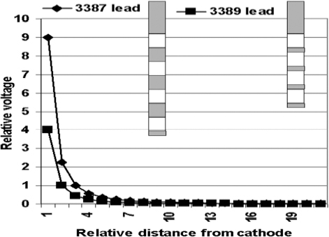
Fig. 13.12 Schematic representation of the relative voltage distributions created by the wide-spaced deep brain stimulation (DBS) lead (Medtronic model 3387, Medtronic, Inc., Minneapolis, MN) and the narrow-spaced DBS lead (Medtronic model 3389). As can be seen, the wider-spaced DBS lead can produce more intense voltage fields. Further, the wider-spaced DBS leads can produce all the same electrical field produced by the narrow-spaced DBS lead.
Deep Brain Stimulation Active Contact Configuration, Safety, and Battery Life
As described earlier, different active contact configurations can have a marked impact on the electrical voltage field. In addition, the different configurations can have a marked impact on the amount of electrical energy dumped into the brain, which has safety consequences. There is a limit to how much electrical energy can be safely given, and that is 30 μC per cm2 per phase. Thirty microcoulombs refers to the amount of electrons (ions) passed into the brain with each stimulation pulse. Per cm2 refers to the surface area of the active contact. Per phase refers to one component of the stimulation pulse (Fig. 13.13). Note that the description of contact being cathode (negative) or anode (positive) is a misnomer. All contacts are cathode during the first phase and then anode during the second phase or vice versa (Fig. 13.13). This is because the stimulation pulse is bi-phasic; that is, it contains two phases where the polarity (negative and positive) reverses.
Unfortunately, the operator does not directly control the amount of energy (in coulombs) injected into the brain with each stimulation pulse. Rather, the operator controls the voltage, which is indirectly related to the amount of energy injected into the brain per unit time (current measured in amps) through Ohm’s law (Fig. 13.7). The relationship of the current to the voltage is mediated by the impedance (resistance). Thus, if the voltage is kept constant but the impedance is markedly reduced, then there will be a marked increase in the current being delivered to the brain.
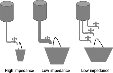
Changing the DBS active contact configurations can have a marked effect on the impedances. For example, the impedance going through any single contact may be quite high, thereby limiting the amount of current for any given voltage. However, if multiple active contacts are used, such as multiple cathodes or multiple anodes, the overall impedance can become very low (Fig. 13.14). For example, using the computer simulator of the currently commercially available DBS programmer (8840 N’Vision Clinician Programmer, Medtronic, Inc., Minneapolis, MN) configured as bipolar with contact 0 the cathode and contact 3 the anode, voltage of 4, and a pulse width of 270 produces an impedance of > 2000 ohms, and DBS is within safety limits. Increasing the number of cathodes to contacts 0, 1, and 2 and keeping contact 3 as the anode results in the impedance becoming 75 ohms and the electrical charge injected into the brain exceeds the safety limit. Thus it is important to know the impedance of any configuration to assure that the amount of current being delivered to the brain is within safety limits. The manufacture of the currently commercially available devices (ww.medtronic.com) provides a nomogram that relates pulse width, voltage, and impedance to the amount of electrical energy injected into the brain with DBS and defines regions that are within the safety limits (Fig. 13.15).
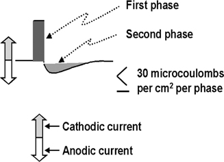
Fig. 13.13 Schematic representation of the stimulus pulse of currently commercially available impulse generators (Soletra and Kine-tra, Medtronic, Inc., Minneapolis, MN). The initial phase has a high voltage (that voltage set by the programmer) of a short duration (the pulse width set by the programmer), whereas the second phase has a lower voltage and longer duration.
The Model 8840 N’Vision Clinician Programmer provides a warning if the selected stimulation parameters exceed the safety limit. However, the programming device does not measure the current densities nor can it calculate them based on the voltage because the programming device does not know what the impedances are. The warnings provided by the programming device are based on the assumption that the impedance is 500 ohms. This means that if the actual impedance of the DBS configuration is 500 ohms, the warnings are accurate. However, if the impedances are significantly greater than 500 ohms, then the device will give a false-positive warning. Indeed the foregoing example where the DBS was configured as bipolar with contact 0 the cathode and contact 3 the anode, voltage of 4, and a pulse width of 270 producing an impedance of > 2000 ohms would give a safety warning although the normogram indicates being within safety limits. Although this may be the safer situation for the patient, it does risk not using higher DBS voltage and pulse widths that could be necessary to achieve symptomatic control and provide the patient with optimal benefit from DBS. Alternatively, the actual impedances may be lower than the estimate of 500 ohms, for example, where there are several active DBS contacts as already described.
The programmer can determine whether the current densities being delivered by a specific DBS configuration and parameter set are within the safety limits by consulting a nomogram (Fig. 13.15) that relates pulse width and voltage to the amount of current delivered at a given impedance. The programmer must first determine the impedances of the specific therapeutic DBS configuration and stimulation parameter set unique to the patient by using the “therapeutic measurements” function and not the “electrode impedance” function on the Model 8840 N’Vision Clinician Programmer.
Related posts:


Stay updated, free articles. Join our Telegram channel

Full access? Get Clinical Tree


