Chapter 149 Dorsal Thoracic and Lumbar Simple Hook-Rod, Wire, and Wire-Rod Techniques
The first internal fixation device was designed by Harrington in 1947, a period in which the number of patients with poliomyelitis-induced scoliosis was growing, and there was dissatisfaction with the current management of corrective casting. The device was designed to correct scoliotic curvatures and halt progression of cardiopulmonary compromise in affected patients. Initial attempts consisted of screw fixation of facet joints in the corrected position. The results appeared promising, but early beneficial results were short-lived. Facet screw failure led to the development of a hook-and-rod construct, in which hooks were attached to the dorsal elements and held in place with a combination of distraction and compression forces. The clinical results of Harrington’s new system were published in 1962.1–3
The Harrington system offered the first internal fixation device for the correction of scoliotic deformities. The system was quickly adopted by spine surgeons and applied to various conditions, including trauma, neoplastic disease, fixed deformities, and degenerative disorders.2,4,5
The Harrington system, although versatile, was plagued with inherent problems. The system was limited in its design, which allowed for only two points of fixation. Failure at any single hook site led to failure of the entire system.6 However, the system has been modified over the years.
In the early 1970s, Luque was faced with an impoverished community in which postoperative bracing was impossible. From these circumstances arose the concept of segmental spinal instruumentation. The Luque system consisted of straight, L-shaped, or rectangular rods attached to lamina via sublaminar wires.7 The advent of segmental spinal instrumentation addressed the main problem associated with the Harrington system that had only two points of fixation. Initially, sublaminar wires were used to supplement the Harrington system.4–6 This innovation was followed by interspinous wiring techniques, such as Wisconsin wires and Dummond buttons. The original Harrington rod was rigid and difficult to contour, and the rounded caudal rigid tip failed to prevent rotation. This shortcoming led to the development of the square-ended Moe rod, which allowed rod contouring. The three-pointed bending force, which a contured rod provides, was enhanced further by the development of the Edward sleeve.6,8 The Harrington system, although often replaced by newer universal spinal instrumentation systems, can be used to stabilize thoracic and lumbar fractures that result from axial loading and in which the anterior longitudinal ligament is intact.
Harrington Distraction Fixation
Technique
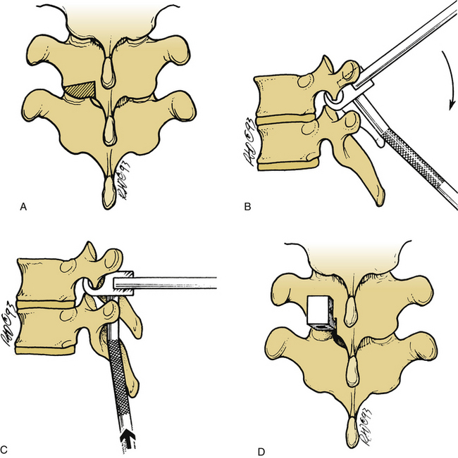
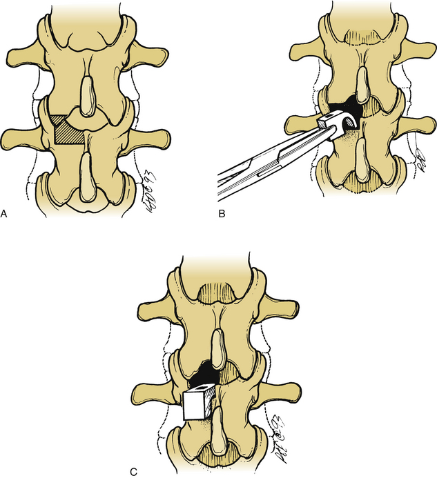
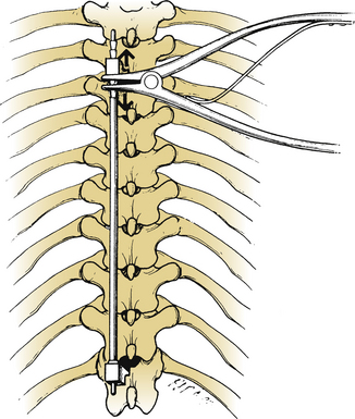
The lamina is conformed to allow seating of the rostral ratcheted hook, typically a no. 1253 hook. A no. 1251 hook can be used as a starter hook, which can be replaced by a no. 1253 hook, a keeled hook, or a bifid no. 1262 hook. The hook is inserted to follow the angle of the facet joint and is gently tapped into position. A well-seated hook should lie orthogonal to the spine (Fig. 149-1). The caudal hook site is generally located two levels below the level of the injury. The interlaminar region at this level is enlarged with a Kerrison rongeur. The ligamentum flavum is excised, and the rostral margin of the lamina is conformed to accommodate the caudal hook, usually a no. 1254 round-hole hook or a no. 1201 square-hole hook (Fig. 149-2). Square-hole caudal hooks are most commonly used because they allow contouring of the rods and minimize rotation. A construct undergoing distraction is depicted in Figure 149-3.
Segmental Fixation
Segmental fixation of the Harrington system has been shown to increase stability.5,6 Segmental fixation can be achieved with either sublaminar wires or cables or interspinous techniques.5,9 When sublaminar fixation is chosen as a means of segmental fixation, use of the cables should be considered because they are stronger and more flexible, and the incidence of neurologic complications may be decreased. Placement of a sublaminar wire or cable can be accomplished by removing the interspinous ligament and performing an interlaminar laminotomy along the midline at each level that is to be instrumented. The ligamentum flavum is removed with a Kerrison rongeur, and the dura mater or epidural fat is visualized. Adequate removal of the ligamentum flavum ensures easy passage of the sublaminar wire or cable.
Interspinous Segmental Instrumentation
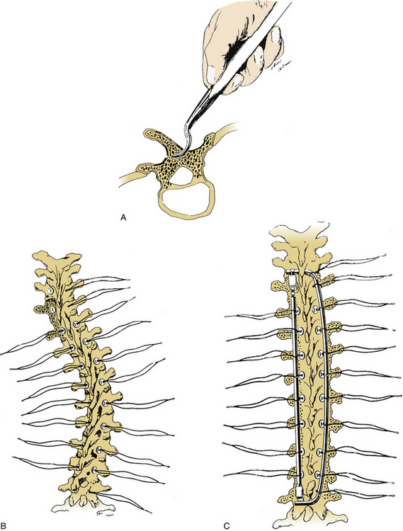
Interspinous segmental instrumentation can also be used to supplement the strength of the construct.3 A single hole is made at the base of each spinous process to be instrumented, with a curved awl, a bone tenaculum, or a drill. Beaded Wisconsin wires, with attached Drummond buttons, are passed through the base of the spinous process from each side. Once it is through the base of the spinous process, the beaded Wisconsin wire is passed through the contralateral Drummond button. The Wisconsin wires are pulled tight until the Drummond bottom fits snugly against the base of the spinous process. The beads are then cut. When the rods are in place, the wires are tightly secured to the rods, and the excess wire is removed. The free wire ends are bent to provide a low profile (Fig. 149-4).
Stay updated, free articles. Join our Telegram channel

Full access? Get Clinical Tree


