Fig. 2.1
Different types of electrodes. (a) Gold cup electrode. (b) Plastic cup electrode CT/MRI compatible. (c) Pad electrode. (d) Ring electrode. (e) Subdermal electrode (also available as MRI/CT compatible). (f) Auto-adhesive, pre-gelled, disposable electrode. (g) Dry electrode (g.SAHARA®, G-tec medical engineer, reprinted with kind permission)
Cup electrodes have typically a diameter of 4–10 mm and a hole on its top to allow the application of saline gel (for conduction), as on a typical EEG. For monitoring, these have to be fixed on the scalp with an adhesive plaster (Fig. 2.1a). Of note, after 10–14 days of recording, 2–3 days without electrodes (“electrode holiday”) are advisable to prevent skin damages. These electrodes are recommended by the IFCN for EEG monitoring (Chatrian et al. 1996). CT-/MRI-compatible plastic cup electrodes are also available (Fig. 2.1b).
Pad electrodes held in place with a rubber headset are convenient because they allow a precise placement even in patients with small skull defects or skin scars and avoid the fastidious work of standard cup electrodes fixation/removal. However, they are neither suitable for EEG monitoring, nor for patients with significant skull defects (Fig. 2.1c).
Ring electrodes fixed with electrode holder on a textile cap allow a rapid placement (Fig. 2.1d). Moreover, commercially available caps are built according to the international 10–20 system (see below). However, these are not suitable for patients with skull defects or recent skin scars and do not assure a satisfying long-term contact for EEG monitoring. This type is also prone to shortcuts between different electrodes, because of the important amount of conductive gel needed.
Subdermal electrodes made of stainless or platinum needles (Fig. 2.1e). Because these are placed under the epidermis, skin abrasion is not necessary. They can be applied very quickly; however, because of their small diameters, they may have a relatively high impedance (Freye E & Levy J. 2005) even though they penetrate the skin. Because of their subdermal position, they are only suitable for comatose patients and may induce local skin infection.
Disposable and pre–gelled pad electrodes (Fig. 2.1f). These could possibly decrease the risk of cross-contamination inherent to standard electrodes and spare time to the technician team by eliminating the time required for disinfection. These electrodes are however difficult to use over the hair.
Dry electrodes (Fig. 2.1g). This new type of electrodes is now commercially available but not routinely used in clinical practice. Their name is due to the fact that neither gel nor skin preparation is needed. In view of their quick application and good impedance, this type of electrodes may be more frequently used in the future.
Every electrode type has thus its advantages and disadvantages summarized in Table 2.1, but cup electrodes fixed on patient’s scalp with an adhesive conductive paste, represent probably the most suitable type for EEG monitoring.
Table 2.1
Pros and cons for every type of EEG electrode
Electrode type | Pros | Cons |
|---|---|---|
Cup electrodes | Good impedance | Time consuming |
Can be used for long-term monitoring | Technician needed | |
Possible electrode placement modification if required (skull defects, skin scar, clip, etc.) | ||
Recommended by the IFCN | ||
CT-/MRI-compatible electrodes available | ||
Pad electrodes | Good impedance | Only some hours of good recording |
Relatively fast setup | Not suitable for patient with significant skull defect | |
May be used on patients with minor skull defect | Technician most often needed | |
Possible electrode placement modification if required (skin scar, clip, etc.) | ||
Ring electrodes | Good impedance | Only some hours of good recording |
Fast setup | Prone to bridge because of the important quantity of conductive paste needed | |
Not suitable for patients with skull defects | ||
Electrode placement modification is impossible | ||
Technician most often needed | ||
Needle electrodes | Fast setup | Only suitable for comatose patients. May have a relatively high impedance because of small diameter |
CT-/MRI-compatible electrodes available | Technician/nurse most often needed | |
May be prone to skin infection | ||
Disposable and pre-gelled electrodes | Fast setup | Difficult to use over hair, so full scalp coverage is impossible |
No risk of cross-contamination | Fair impedance | |
Can be placed by any healthcare provider with minimal teaching | ||
Dry electrodes | Good impedance | Cost |
Fast setup because no skin preparation is needed | Mostly used for current research | |
Not widely used in clinical practice |
2.1.3 Electrode Position and Montages
2.1.3.1 Electrode Position: The 10–20 System
The IFCN proposes a unified electrode nomenclature and electrode placement, called the 10–20 system (Klem et al. 1999), which includes 21 electrodes providing a good scalp coverage. This international and widely adopted system should be used on every scalp EEG in the ICU. The electrodes are named with a letter, representing the anatomical region (Fp = frontopolar, F = frontal, C = central, P = parietal, T = temporal, and O = occipital), and a number (even numbers on the right and odd numbers on the left; midline electrode is called z (zero)) (Fig. 2.2). The system is called 10–20 because each electrode is separated with 10 or 20 % of an anatomical distance.
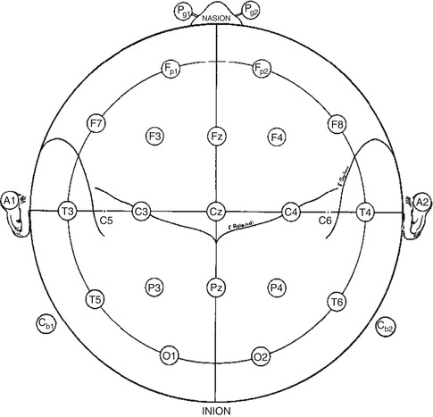

Fig. 2.2
A single plane projection of the head, showing all standard positions according to the 10–20 system (Adapted from Klem et al. (1999). © International Federation of Clinical Neurophysiology. Reprinted with kind permission from the International Federation of Clinical Neurophysiology)
The guidelines edited by the IFCN provide detailed methods of the electrode placement based on anatomical landmarks (Klem et al. 1999). The first step is to place the midline chain of electrodes, Fpz, Fz, Cz, Pz, and Oz (Fig. 2.3), by measuring the distance between the nasion and the inion through the vertex. Of note, Fpz and Oz positions will not be covered by an electrode. The next step is to measure the coronal distance from the left preauricular point to the right one through Cz. This will provide the position of T3 (also named T7), C3, C4, and T4 (also named T8) (Fig. 2.4). Then, in order to obtain the position of Fp1, F7, T5 (also named P7), and O1 on the left and Fp2, F8, T6 (also called P8), and O2 on the right, a circumferential measurement of the head through Fz, T3, Oz, and T4 should be obtained (Fig. 2.5). Finally, F3 should be placed at the intersection of Fp1–C3 and F7–Fz, F4 at the intersection between Fp2–C4 and Fz–F8, P3 at the intersection of C3–O1 and Pz–T5, and P4 at the intersection between C4–O2 and Pz–T6. A cerebral or extracerebral reference electrode, a ground, and an electrocardiogram should be placed eventually.
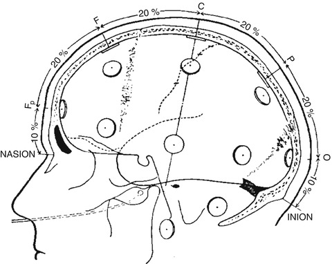
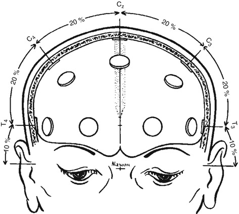
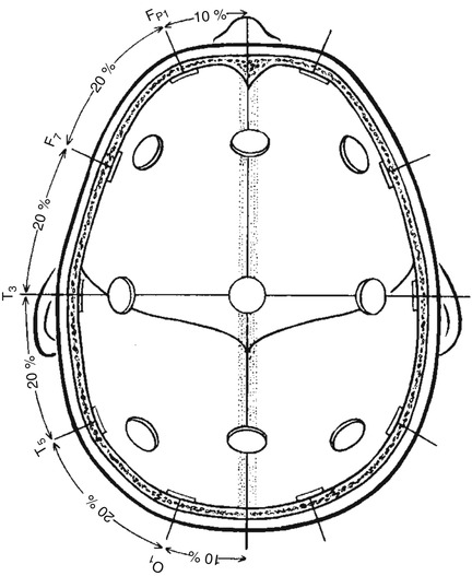

Fig. 2.3
Lateral view of the skull to show methods of measurement from nasion to inion at the midline. Percentages indicated represent proportions of the measured distance from the nasion to the inion (Adapted from Klem et al. (1999). © International Federation of Clinical Neurophysiology. Reprinted with kind permission from the International Federation of Clinical Neurophysiology)

Fig. 2.4
Frontal view of the skull showing the method of measurement for the central line of electrodes as described in the text (Adapted from Klem et al. (1999). © International Federation of Clinical Neurophysiology. Reprinted with kind permission from the International Federation of Clinical Neurophysiology)

Fig. 2.5
Superior view with cross section of the skull through the temporal line of electrodes (Adapted from Klem et al. (1999). © International Federation of Clinical Neurophysiology. Reprinted with kind permission from the International Federation of Clinical Neurophysiology)
2.1.3.2 Montages
The types of montages are highly variable in every center. The same montages used for routine EEG should be used. Some bipolar and referential arrangements are proposed by the ACNS (American Clinical Neurophysiology 2006a) and can be easily applied. Of note, the most popular is the traditional longitudinal bipolar montage (also known as “the double banana”) (Fig. 2.6). The use of the 21 electrodes provided by the 10–20 system offers good scalp coverage, but, in selected cases, montages with fewer electrodes can be used. To determine brain death, for example (this only applies in certain countries), the distance between electrodes should be at least 10 cm. The ACNS recommends a bipolar montage using 10 electrodes, for example, F7-T5, F8-T6, F3-P3, F4-P4, and Fz-Pz (American Clinical Neurophysiology 2006b).
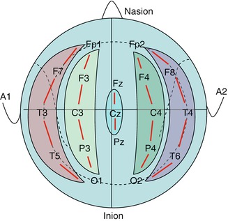

Fig. 2.6
The longitudinal bipolar or the “double banana” montage
2.1.3.3 Other Montages/Electrode Positions
Anterior Temporal Electrodes
If the temporal regions are an important issue, two additional electrodes can be added to maximize the anterior temporal lobe coverage. These are called T1 (left) and T2 (right). They are placed one cm above the line cut at the third next to the ear, between the external angle of the eye and the preauricular point.
Extracerebral Electrodes (“Polygraphic Recording”)
Additional electrodes placed near the eyes (to record eye movements), on selected muscles (to record particular body region of interest, such as the tibial and the submental regions) and respiratory electrodes (measuring the movements of chest and abdomen) can also be added. These additional electrodes can be helpful to discriminate between cerebral or extracerebral activities and artifacts. A routine extracerebral electrode (pair) is the EKG.
“Subhairline” Montages
Because most of the centers cannot provide 24/7 EEG technician coverage, some simple montages that can be placed with auto-adhesive electrodes have been developed. To avoid scalp and hair issue, disposable and pre-gelled pad electrodes are placed just below the hairline. Of note, EKG electrodes can be used for this purpose. A study demonstrated a sensitivity of only 68 % but a 98 % specificity for seizure detection using a 4-channel commercial ICU bedside monitoring system (Young et al. 2009) (Fig. 2.7). Another study retrospectively recreated a digital “subhairline” EEG from standard 10–20 EEG by using only 8 electrodes: Fp1, F7, T3, and T5 on the left and Fp2, F8, T4, and T6 on the right. The sensitivity for seizure detection was only 72 % (Kolls and Husain 2007). The addition of Cz seems to increase the sensitivity up to 92 % (Karakis et al. 2010).
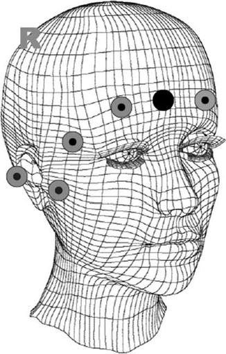

Fig. 2.7
Example of a “subhairline montage” (Adapted from Young et al. (2009), Figure 1, ©Humana Press Inc. Reprinted with kind permission from Springer Science + Business Media B.V.)
Disposable Devices
Some disposable and quickly applicable “electrode systems” have been developed. For example, pre-gelled EEG headpieces, embedded with integrated wiring, are commercially available (Fig. 2.8). However, these only provide about 4 h of reliable recording with usually less than 21 scalp electrodes; they cannot be used on patients with skull defect, and, because of the disposable nature, related costs should be considered. It seems reasonable to consider this system when a standard electrode placement is not available and the EEG information is needed immediately.
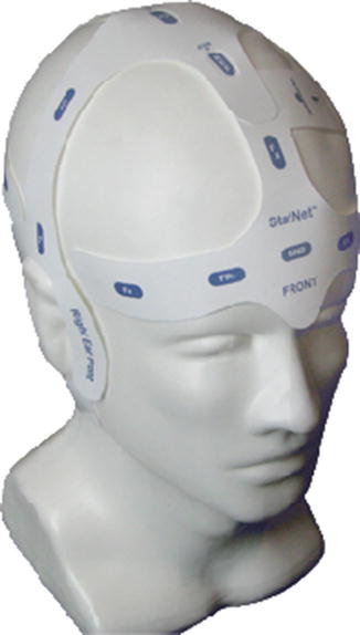

Fig. 2.8
Example of a disposable auto-adhesive EEG device (StatNet™, HydroDot Inc., reprinted with kind permission)
2.1.4 Jackbox, Amplifiers, and Filters
2.1.4.1 Jackbox
Each electrode’s wire will be plugged in a jackbox (Fig. 2.9). Many devices often surround the ICU beds; therefore, a small jackbox that can be placed near the patient’s head is recommended. The jackbox should also be fixed and possibly sealed into a waterproof packing to avoid damage (Herman 2013). The jackbox contains the amplifiers; according to the IFCN (Ebner et al. 1999), at least 23 connectors (amplifiers) are required for clinical practice. However, larger capacity input systems are available (for higher special resolution and extracerebral electrodes).
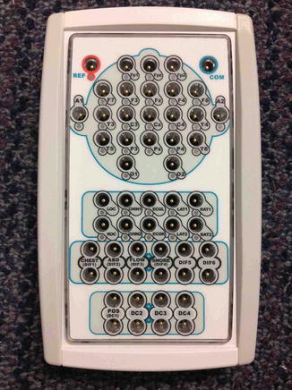

Fig. 2.9
An example of an EEG jackbox
2.1.4.2 Amplifiers
EEG amplifiers have two functions: discrimination and amplification (Fisch 1999). Discrimination is the ability to amplify the difference between two electrical potentials: the amplifier will subtract the signal of two different input EEG electrodes, between two adjacent scalp electrodes on a bipolar montage or between one electrode and a common reference for a referential montage, for example. Of note, the subtraction implies that signals common to both subtracted electrodes will be suppressed (this may also give rise to the “electrical bridge,” when an analogous signal between two electrodes is seen as a flat line in a bipolar montage). Artifacts that are common to both electrodes will also be suppressed. In this way, an amplifier can sort out true EEG brain signals and artifacts. This discrimination power can be measured with the “common mode rejection ratio”: the higher this ratio, the higher the discrimination power. With current EEG machines, the specified common mode rejection ratio should be at least >80 dB, typically 100 dB (Ebner et al. 1999). Then, the amplifier will increase the potential difference; this effect is called “gain” or sensitivity. A typical setting for EEG is 7–10 uV/mm.
2.1.4.3 Filters
Filters are used to exclude frequencies that are not generated by the brain. In clinical practice, frequencies of interest are between 1 and 30 Hz. Therefore, the low-frequency filter (synonymous with high-pass filter) should be set at 0.5–1 Hz and the high-frequency filter (or low-pass filter) at 70 Hz. A notch filter of 50 or 60 Hz (depending on the country) for power line artifacts should be used when needed. Of note, it is advisable to start the recording without the notch filter, as electrodes with loose contact to the scalp will tend to show a prominent notch artifact.
Stay updated, free articles. Join our Telegram channel

Full access? Get Clinical Tree


