Fig. 12.1
Problems in EMG prosthetic hand: (a) EMG prosthetic hand with tactile feedback and (b) difficulties in EMG classification
Activities of daily living (ADL) tests are applied for determining the utility of adaptable EMG prosthetic hands. They demonstrate the performance of the proposed system when operated in a kitchen, during writing, and when holding cups for drinking/eating, as shown in Fig. 12.2.
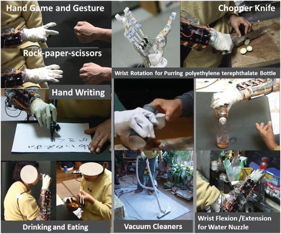
Fig. 12.2
Prosthetic hand for use in activities of daily living
1.
General operation
Opening and shutting doors (with round knobs), pouring a beverage from a polyethylene terephthalate bottle into a glass, drinking water from a glass, holding a teacup, holding a pen, picking up small objects by using the index finger and the thumb, holding vacuum cleaners using a cylindrical grip and wrist motions, performing a handshake, and touching and distinguishing a ball from a pen when gripped.
2.
Cooking
Using a kitchen knife, pouring oil from a bottle on to a frying pan, manipulating a faucet, holding a frying pan, holding a scooped ladle, and putting the contents of a teacup into a frying pan.
3.
Gestures
Playing janken, pointing, beckoning.
12.2.2 Device Design for ES for Functional Recovery of Motion
Stimulations can be produced by using an implant, percutaneous implant, or surface electrode (Fig. 12.3).
Fig. 12.3
Type of electrode: (a) implant electrode, (b) percutaneous implant electrode, and (c) surface electrode
ES implants have mainly been studied in the USA. Peckham developed a “Free Hand System,” an ES method with implant electrodes, and succeeded in recovering upper limb exercise functions that were lost owing to paralysis due to a cervical cord injury [9].
With regard to percutaneous implants, Handa developed “FESMATE” using percutaneous implant electrodes [10] to manipulate the hand so as to produce artificial motions for eating and drinking, etc. He succeeded in recovering upper limb exercise functions that were lost owing to paralysis due to a cervical cord injury as well as lower limb exercise functions in hemiplegia and paraplegia. Shimada developed “Akita Stimulator II,” which consists of 32ch percutaneous implant electrodes, and he tested walking and standing motions [11].
Implant electrodes are mainly used for severe cases of paralysis; however, they require surgical operations and cause considerable mental and physical stress to users. In contrast, surface ES is noninvasive and is therefore preferable to implants. However, while surface ES easily works on sensors on the skin, it does not have an impact on muscle contraction, and it may occasionally cause pain. The human body is capacitive, and therefore, a direct electric current passes through the skin surface without coming into contact with the deep-lying muscles.
The capacitive nature can be exploited using a basic theory of electrical circuits. Kots discovered a biphasic ES waveform with a high-frequency sinusoidal wave being modulated by a low-frequency wave, called as “Russian current” [12]. This waveform can flow through the deep-lying muscles, and therefore, it is used in many ES devices. Recently, Bioness Inc. developed H200TM and L300 TM for supporting grasping motions and improving equinus foot with a limited ankle joint.
12.2.3 ES for Neurorehabilitation
Synchronization of the exercise intention and sensory feedback is of utmost importance for rehabilitation. Many ES systems consist of a brain–machine interface (BMI) [13]. A BMI is a type of man–machine interface that provides a direct connection from brain activities to the external device.
A BMI has two main functions. One is the signal input part. It can estimate the user image of exercise by measuring the brain activity and deciding the stimulation process for exercise. Studies have successfully employed electrocorticograms (ECoGs), electroencephalography (EEG), functional near-infrared spectroscopy (fNIRS), and fMRI for estimation. Integrated Volitional control Electrical Stimulation (IVES), developed at Keio University, can be used to detect the generation of EMGs and produce stimulations. Hybrid Assistive Neuromuscular Dynamic Stimulation (HANDS) can be used to improve upper limb function [14].
The other is the examination part. It can measure the brain activity and examine the effect of stimulation. Measurement results obtained when paralyzed people train for grasping motions and moving objects via upper limb functions or for treadmill and cycling motions via lower limb functions with ES suggest that ES is associated with brain activation [15]. A study conducted at Akita University aimed to reduce one’s burden due to a massive stroke using a rowing machine, and this approach was found to be effective [16].
As discussed above, conventional studies have realized considerable advancements in ES devices and rehabilitation. However, an ES-based rehabilitation system has not yet been established. In this study, we have tried to develop an ES-based device for rehabilitation (Fig. 12.3).
12.2.4 BMI Research Overview
A BMI is a type of man–machine interface that provides a direct connection from brain activities to external devices. Its use has been studied for overcoming the paralysis of the sensory motor system of limbs; furthermore, many research institutes and universities have studied its use for lower leg rehabilitation. Brain activities are detected from the sensory motor area in the cerebral cortex. Signals can be detected invasively or noninvasively. Invasive approaches include the use of a multichannel needle-shaped sensor inserted into the cerebral cortex or a surface sensor such as an ECoG. Noninvasive approaches include the use of EEG, fNIRS, or fMRI. Prof. Tanaka developed a wheelchair control system, which is a representative noninvasive output-type BMI approach using EEG [17]. Noninvasive approaches are ideal because they are safe and comfortable; however, their spatial resolution and signal-to-noise ratio are not suitable for practical control. As a result, many studies continue to focus on invasive approaches.
An output-type BMI is used for the intuitive control of an external device instead of limbs, and an input-type BMI is used for the recovery of central nervous system function by using an external device. Initial studies on BMI in the USA focused on invasive signal detection of brain activity, and they achieved highly successful control of a prosthetic hand [18, 19] with good spatial resolutions and signal-to-noise ratio; however, degeneration and necrosis limit long-term use [20, 21]. To overcome this problem, an ECoG was developed. This is an invasive signal detection method involving the use of a surface electrode on the cerebral cortex under the dura mater, and it shows precise spatial resolution with good signal-to-noise ratio. ECoGs have been used to realize output-type BMI systems for two-dimensional cursor control and motion prediction of the upper arm [22–26].
Studies on noninvasive input-type BMIs have focused on rehabilitation. Prof. O’Donnell studied the improvement of QOL using a real-time bidirectional BMI [11]. The Cleveland FES Center studied the functional recovery of a spinal cord injury using a functional ES for practical use [15, 27–29]. Mixed training using FES and a walking-assistance device was applied for enhancing spinal cord injury (SCI) rehabilitation [30]. Ellaway et al. at the Royal National Orthopaedic Hospital used a walking-assistance treadmill with a counterweight for gravity with transcranial magnetic stimulation (TMS) on the cerebral cortex for SCI rehabilitation. Conway used Lokomat, functional electrical stimulation (FES), and TMS for rehabilitation [31, 32]. Keio University has been engaged in a practical collaborative research project encompassing the medical and engineering fields [33]; they have successfully achieved hand rehabilitation through a BMI power-assistance method for functional recovery by using FES and a mechanical motion supporting device.
12.3 Relationship Between EMGs and ECoGs
The human musculoskeletal system is the best “device” for realizing the brain’s motor intentions. Unfortunately, the body image presented by a BMI robot arm to the brain differs considerably from that presented by the native arm, because the former cannot reflect motor intentions as faithfully as the musculoskeletal system. On the other hand, an EMG prosthetic arm estimates motor intentions from the activities of a patient’s residual muscles. The muscle is superior to the BMI robot arm as a “device” to reflect the brain’s motor intentions. In fact, an EMG prosthetic arm generally realizes more sophisticated motions than a BMI robot arm. However, our latest study, in which we compared the muscle and the brain activities of monkeys, suggested that EMG prosthetic arms might not always be superior to BMI robot arms in the estimation of the brain’s motor intentions. The superior arm would depend on the abstract level of the motor intentions.
12.3.1 Abstract Level of Motor Intention
Motor intentions are divided into different types depending on the different abstract levels. Consider the reaching motion of monkeys, such as a self-feeding motion, as an example. This motion consists of the following movement sequence:
Reaching forearm to an object
Grasping the object
Returning forearm while grasping the object
Various types of physical values such as the EMGs of each muscle, grip force, angular velocities of joints, three-dimensional wrist positions, and hand postures can be measured. Based on the interpretation of these physical values, the movement phase (e.g., waiting, reaching, grasping, resting) can be considered as the motor intention of the higher abstract level. Of course, the monkey’s intention in performing the reaching movement is one of the motor intentions of a higher abstract level. In this study, we consider motor intentions of this abstract level as task-oriented motor intentions.
According to the theory of localization of brain functions, information from different abstract levels is processed in different parts of the cerebral cortex. On the other hand, the planning, control, and execution of voluntary motions (VMs) are processed in the motor cortex. In this book, the abstract level of motion intention that will appear as brain activity is discussed based on the brain and the muscle activity measured from a monkey.
12.3.2 Experimental Subject
A monkey (Macaca fuscata) implanted with EMG and ECoG electrodes is used as the experimental subject. EMG and ECoG signals are recorded simultaneously using a Neural Data Acquisition System OmniPlex (Plexon). The EMG signals are recorded as auxiliary analog inputs of OmniPlex. The band of the signals is limited by a low-pass filter (250-Hz cutoff), and the signals are recorded with a 500-Hz sampling rate.
The target muscles, which are related to the locomotion of the upper limb and hand, for measuring EMGs are listed in Table 12.1.
Table 12.1
Target muscles for measuring EMGs
Target muscle | Mainly moving joint |
|---|---|
PM (Pectoralis major) | Shoulder |
DP (Deltoid posterior) | |
TLoH (Triceps long head) | Elbow |
TLaH (Triceps lateral head) | |
BLH (Biceps long head) | |
B (Brachioradial) | |
ECR (Extensor carpi radialis) | Hand |
EDC (Extensor digitorum communis) | Index, little finger |
FDP (Flexor digitorum profundus) | Finger |
FCU (Flexor carpi ulnaris) | Hand |
APL (Abductor pollicis longus) | Thumb/hand |
AP (Adductor pollicis) | Thumb |
Figure 12.4 shows the alignment of ECoG electrodes. The target area is around the left motor cortex, including the premotor area (PMA), primary motor cortex (M1), and primary somatosensory cortex (S1).
Fig. 12.4
Alignment of ECoG electrodes around motor cortex
12.3.3 Modeling of Reaching Task
We designed a lever operation task as a reaching task based on the self-feeding motion of monkeys. Figure 12.5 shows an outline of the task. The monkey is kept under restraint on a chair. At first, a push button (home button) is set up under the monkey’s right hand and a lever is placed in front of the monkey. A tube is introduced into the mouth of the monkey and liquid reward is given through a pump. The pump is actuated when the subject pulls a lever after the home button is pushed. The monkey is adequately trained in performing this task.
Fig. 12.5
Modeled reaching task
12.3.4 Preprocessing of EMG Signals
The measured EMG signals are transformed to iEMGs (integrated EMGs) as follows:
where S m (t) is the signal measured by the mth EMG electrode at time step t; M m (t), the iEMG of the mth channel of the EMG; and L, the term of consideration. Because the iEMG strongly correlates to the exerted muscular force and is robustness to white noise, it serves as an appropriate index of muscular activity.
(12.1)
12.3.5 Preprocessing of ECoG Signals
We already know that some frequency bands are effective for determining the locomotive state of a subject [34]. Table 12.2 shows the range of each frequency band.
Table 12.2
Range of each frequency band
Band | Range (Hz) |
|---|---|
Alpha α | 7–11 |
Beta β | 20–30 |
High-gamma1 γ L | 80–150 |
High-gamma2 γ H | 150–250 |
Previous studies have shown that high-gamma power strongly correlates to locomotive events in the same way as EEGs or LFPs. However, the range of the high-gamma band differs in each paper. To cover these different definitions, we separate the high-gamma band (80–250 Hz) into two ranges: γ L (80–150 Hz) and γ H (150–250 Hz). The power of each band is decided by calculating the power spectrum by short-time Fourier transform (STFT). The window size L equals.
12.3.6 Partial Least Squares Regression
We estimate EMGs from ECoG signals by partial least squares (PLS) regression [35]. Because of the relationship between the spatial resolution of ECoG electrodes and the distances between adjacent electrodes, the signals obtained from the electrodes are collinear. In regression analysis, collinearity makes it difficult to decide the values of regression coefficients and reduces the prediction accuracy. On the other hand, PLS regression serves to remove collinearity and improves the precision of regression analysis.
In this study, PLS regression is performed by the following procedure. First, the feature vectors of ECoGs are constructed as follows:
where x i (t) (i = 1, 2, …, N) is the sub-vector of the feature vector x i (t). As defined in Eq. (12.1), each element of x i (t) indicates the power of the corresponding band. These elements are considered explanatory variables in PLS regression.
where y(t) is iEMG of the target muscle at time step t, x′ k (t) is the kth element of latent variable vector x′(t) corresponding to x(t), β k (k = 0, …, r) is the kth regression coefficient, and E(t) is the error term. The vector x′(t) is calculated with the coefficient matrix A to maximize the covariance of y and x′.
(12.2)
(12.3)
(12.4)
12.3.7 Experimental Results
We achieved data sequence including 100 of regular trials. The coefficient matrix A is decided by using the data including 90 trials, and prediction accuracy is evaluated with sequential data including ten trials except the data used to decide the coefficient matrix A.
An example of prediction during 2 s is shown in Fig. 12.6. The solid line represents actual values and dashed line represents predicted values. In most cases, trends and peak values are matched well. Though the peak time shift is admitted in some cases, for example, FCU, the rise time is not so largely changed in such cases.
Fig. 12.6
Examples of actual and predicted values for each muscle
For quantitative evaluation, correlation factor and root-mean-square error (RMSE) for each muscle are shown in Table 12.3. All correlation factors are significant at the 95 % confidence level. Of them, nine factors exceed the value, which can be considered highly correlated (0.7). In the case of TLaH, BLH, and ECR, the correlation values are not so high. However, they make not so much difference comparing RMSE.
Table 12.3
Comparative tables of correlation factor and root-mean-square error for each muscle
Correlation factor | Root-mean-square error | ||||
|---|---|---|---|---|---|
PM | DP | TLoH | PM | DP | TLoH |
0.88 | 0.83 | 0.82 | 0.12 | 0.17 | 0.20 |
TLaH | BLH | B | TLaH | BLH | B |
0.59 | 0.55 | 0.85 | 0.21 | 0.21 | 0.16 |
ECR | EDC | FDP | ECR | EDC | FDP |
0.64 | 0.79 | 0.89 | 0.18 | 0.21 | 0.13 |
FCU | APL | AP | FCU | APL | AP |
0.75 | 0.83 | 0.71 | 0.20 | 0.19 | 0.18 |
As mentioned above, it seems that the iEMG prediction by PLS regression works well. However, some irregular patterns are found during the sequence which has period stability. Figure 12.7 shows the typical regular iEMG pattern and the irregular iEMG pattern during ten trials of continuous reaching motion. In 9 of 10 trials, the regular pattern of actual iEMG is observed. However, a trial which is one of ten trials, irregular pattern is observed shown in Fig. 12.7. On the other hand, the reaching task is performed properly in both of these cases. It has period stability from the task-oriented point of view. Similarly, the brain activity has stability also. The wave form of predicted values is more similar to the regular actual iEMG pattern than irregular one. Though the activity of motor cortex is regular, because of disturbance during reaching motion and so on, the synergy which differs from typical patterns is produced.
Fig. 12.7
Comparison of actual and predicted values of iEMG with typical patterns. (a) Regular pattern and (b) irregular pattern
We have some other example of irregular iEMG pattern on the reaching task, case of the deltoid muscle of shoulder shows similar irregular iEMG patterns. This is because the target motion is consisted by many types of synergy of muscles. Therefore the intended motion is realized by one of the synergies.
In this section, we would like to show followings: the iEMG identify concrete motion, and it is easy to understand the motion state of subject, but it is too concrete so that it contains error for motion identification. On the contrary, the ECoG signal gives abstract command for motion, so it is good for identification of intentions of motion.
12.3.8 Discussion
To interpret the phenomenon pointed out above, we describe about contribution of the cerebellum to motor function which is clarified by M. Kawato et al. as follows [36]:
1.
When the environment is unstable and training for the locomotion is not enough, feedback control is performed.
2.
When the environment is predictable and training is enough, feedforward control by the internal model constructed in the cerebellum is performed.
The brain changes these two modes of phenomenon properly and achieves a task. The monkey used as the experimental subject was well trained in the lever operation task. In other words, the monkey performed the motion “programmed” in its cerebellum.
Then, task-oriented motor intentions will be decoded from the cerebral cortex. On the other hand, EMGs will appear as a result of information processing in the central nervous system, which is lower than the cerebellum. In this case, the task-oriented motor intention estimated from the ECoG is superior to that estimated from the EMG.
However, sensory feedback must be carried out with either mode properly. When feedback control is performed, control is not possible without sensory feedback in the first place. Even if feedforward control is performed, the subject will not be able to measure the success or failure of the task. It then becomes necessary to determine the type of relationship that exists among the sensory feedback, brain activities, and measurement of success or failure of the task.
12.4 How Sensory Feedback Works for Body Image Plasticity by MRI Analysis
12.4.1 Sensory Feedback
The feeling that an action is real arises from biological feedback from physical interaction with the environment. Neuroprosthetic applications require an interface between the sensors and the muscle system that provides adequate information about the state of the interaction. This information will provide the user with the necessary confidence to move on to the next action. This study aims to develop a biofeedback system that replaces the functions of sensing and action. We have proposed a multichannel ES technique for practical applications of tactile information feedback and reflex muscle drive (Fig. 12.8). Force Sensor Resister (FSR)-type pressure sensors were placed over the fingertips and the palm of the robot hand to detect the moment at which the hand touches an object when performing a grasping task. The sensors in the fingers were connected in parallel to work as a single pressure sensor; the sensors in the palm are placed at three different positions. Eight different sensing positions are used. The stimulator uses a microcontroller with an analog-to-digital converter to acquire sensor signals; whenever a sensor signal exceeds a preset internal threshold, the robot hand is believed to have touch an object, and an ES signal is generated.
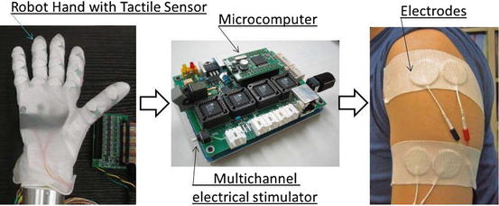
Fig. 12.8
Simple tactile feedback system using multichannel ES for neuroprosthetic hand
This feedback is applied to the prosthetic hand to provide a feeling of grasping. The stimulation electrodes are attached to the remaining body surfaces, e.g., upper left arm or abdomen for a right-hand amputee. The effects of stimulation are revealed through fMRI analysis.
12.4.2 fMRI Analysis
A phantom limb image is a part of the general “body image” of an individual. It also serves as a biological example of brain plasticity by the control of end effectors using sensory feedback. To evaluate the practical use of a prosthetic device, we propose a quantitative index for how the brain adapts to the functions of the device. The effects of adaptation to the prosthetic devices can be observed by changes in the fMRI images. The fMRI analysis reveals interesting phenomena regarding body image plasticity during the training of the EMG prosthetic hand by using sensory biofeedback.
The strength of brain activation is indicated by a stochastic value T under the conditions of certain significance. We focused on the activated patterns at the place in the sensory motor cortex corresponding to the manipulation of the EMG prosthetic hand, and we analyzed the relationship between intensive control and consciousness of tactile feedback. The device usability was evaluated based on the following tactile feedback parameters: place, timing, shape, phantom sensation and mixed sensation, and response and reliability of EMG controller.
To provide visual feedback, we used a video camera to show the prosthetic hand movements inside the fMRI room. The subjects viewed the image through a set of mirrors that reflect the image captured by the video camera. This is necessary because the fMRI cannot be used with the robot hand owing to the strong magnetic forces.
Images were collected using a 1.5-T MRI scanner with a circular polarization coil (Siemens Magnetom Vision Plus, Siemens, Erlangen, Germany). Fifty-four images were obtained per slice over an 8-min period. The images were analyzed by statistical parametric mapping (SPM2) analysis. One subject was recruited for this experiment. Six sessions were performed on different days with a 1-month interval for subsequent tests. Stimuli were displayed on the screen using an LCD projector, introduced into the MRI gantry, and presented to the subject via a mirror mounted on the head coil. One block had six volume scans, and one run consisted of nine blocks that were preceded by six dummy scans. One block consists of three volumes each for the task and the control. The functional images were collected in six runs: one with an echo-planar imaging (EPI) sequence (TR = 3,000 ms, TE = 60 ms, FOV: 192 mm, 64 × 64 image matrix). From each run, 54 sets of 30 slices, 6-mm-thick axial images with 0.6-mm gap between the parallel to the anterior–posterior commissure plane covering the entire brain were acquired. Data analysis was performed using SPM2. fMRI data were realigned and smoothened using a Gaussian kernel applied at intervals of 8 mm, following which statistical analysis was performed using a general linear model with statistical significance defined as corrected P < 0.005.
Related posts:
 Brain–Machine Interfaces in Stroke Neurorehabilitation
The Cognitive Neuroscience of Incorporation: Body Image Adjustment and Neuroprosthetics
Brain–Machine Interfaces in Stroke Neurorehabilitation
The Cognitive Neuroscience of Incorporation: Body Image Adjustment and Neuroprosthetics
 Real-Time Magnetoencephalography for Neurofeedback and Closed-Loop Experiments
 Using Image Adjustments for Producing Human Motor Plasticity
 Effects of Successful Experience and Positive Feedback on Learning and Rehabilitation
 Large-Scaled Network Reorganization During Recovery from Partial Spinal Cord Injury
Stay updated, free articles. Join our Telegram channel

Full access? Get Clinical Tree


