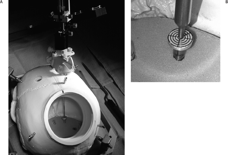
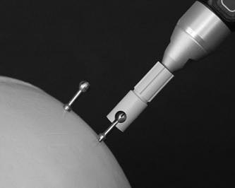
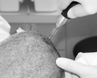
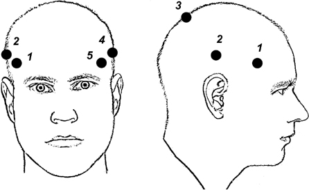
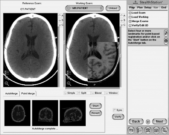
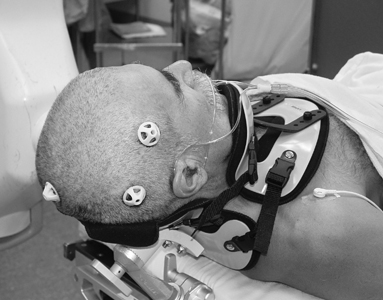
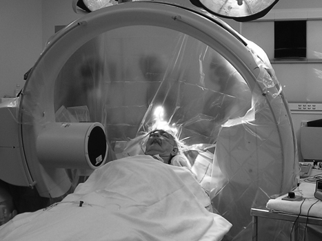
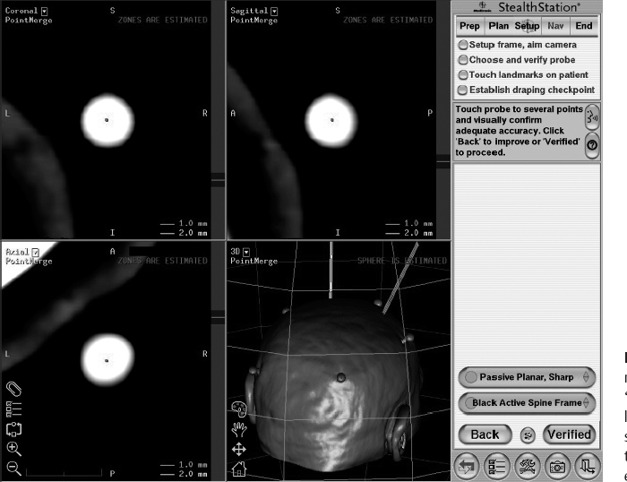
10 Frameless Functional Stereotactic Approaches Jaimie M. Henderson The introduction of image-guided surgical systems over the past decade has had a profound impact on neurosurgical practices. Accurate localization of intracranial targets without the use of stereotactic frames has become commonplace. For procedures such as tumor resection, where real-time feedback regarding intracranial position is helpful, image-guided surgical systems have effectively replaced stereotactic frames. However, trajectory-based functional procedures such as lesioning or stimulation of the deep nuclei for Parkinson disease (PD) and tremor are still widely performed with a frame. The benefit of real-time positional feedback in these procedures is less important than the accurate delivery of a probe to a well-defined target. In addition, functional neurosurgery requires a stable platform to support microelectrode recording and stimulation over many hours and through multiple parallel trajectories. Skin fiducials, as traditionally used for frameless localization, do not provide sufficient accuracy, and instrument holders for biopsy or other applications do not provide sufficient rigidity to meet the demands of true stereotactic localization. Thus new approaches and instrumentation are needed to adapt these systems to use in functional neurosurgery. Although stereotactic frames have proven their utility over many decades of use, there are several theoretical advantages of a fully frameless functional surgery system. Decoupling of imaging from surgery eliminates the need for planning to be done just prior to the procedure, allowing operations to begin on schedule hours or days following planning. For PD patients undergoing deep brain stimulation (DBS) or lesioning, this translates to less time off medication, with concurrent reduction of associated discomfort. Because there is no need to restrain the head, patients are able to move and adjust their position during surgery, further improving comfort and cooperation during the procedure. Sophisticated image-guided surgery systems are employed for planning, registration, and aiming, and the possibility of real-time electrode tracking and integration of multiple information sources becomes possible, improving the situational awareness of the surgeon.1 Because of these advances, there is the potential for a high degree of accuracy.2 Several laboratory studies of image-guided surgical systems demonstrated localization accuracies similar to those achievable with a stereotactic frame.3–7 Preliminary studies have shown the feasibility of using a surgical navigation system in conjunction with an image-guided microdrive to perform functional neurosurgical procedures with acceptable accuracy,8 and a multicenter trial demonstrated equivalent accuracy between a stereo-tactic frame system and an image-guided, skull-mounted platform.9 Frameless systems are increasingly being used as an alternative to frames in stereotactic neurosurgery. There are currently two systems in use for frameless functional neurosurgery. Both rely on skull-implanted fiducials for the highest possible accuracy. Each system is designed to attach rigidly to the skull and must maintain absolute rigidity during the procedure to assure that the probe or electrode does not deviate from the planned target. The STarFix platform (FHC, Inc., Bowdoin, ME) is a custom-fabricated device based on rapid-prototyping technology. Following fiducial placement and imaging, custom software is used to plan the target-entry trajectory. This plan is then submitted to the company, which manufactures a high-grade plastic platform, which attaches to the implanted fiducial markers. The finished custom platform is sent by express mail within 24 to 72 hours. On the day of surgery, the platform is attached to the implanted fiducials after sterile preparation and serves as a trajectory guide. This design trades the flexibility of real-time trajectory adjustment for simplicity and absolute rigidity. The Nexframe from Medtronic Neuromodular IGN (www.medtronic.com/physician/activa) is an adjustable platform that uses a sweep and rotate alignment mechanism. The Nexframe requires a registration and alignment procedure with an image-guided neuronavigation system (Medtronic, BrainLAB, or Stryker). This allows for changes in trajectory should the need arise during surgery. This device has been extensively tested in both the laboratory7 and clinical9 settings, demonstrating equivalent accuracy to a stereotactic frame. The first step in preparing to perform frameless functional interventions is the verification of the image-guided navigational system. Tight quality control is required to achieve optimum accuracy. Ideally, the system should be tested in the same configuration and environment in which it will be used during actual surgery. Position of the camera array and the display screen should be optimized to provide an unobstructed field of view of the surgical field. Studies should be undertaken using a plastic skull phantom equipped with a clearly visible internal target (Fig. 10.1). The planning software is used to choose target and entry points as well as the center of each fiducial marker. All instruments should be checked for geometry errors, with care to verify accuracy during rotation throughout their full range of visibility. Registration and alignment should be simulated with the phantom in a position that would resemble that of a patient during surgery. A rigid probe with absolutely no bend should be used to measure localization error (Fig. 10.1A). Average localization accuracies should be in the 1.25 mm range, with a 99.9% confidence interval of ~4 mm.7 The surgeon must be satisfied with the accuracy of the system during bench testing before moving to clinical use. Fig. 10.1 (A) A plastic skull phantom used for Verification of the image-guided navigation system. A localizing probe is being introduced to the expected target point. (B) A hardened steel mandrel is used to localize the target, which is marked in 1 mm increments to assess radial error in localization. (See Color Plate 10.1A.) As with all stereotactic procedures, imaging is performed prior to the operation with the fiducial system in place (Unibody, Medtronic, Inc.). We utilize a one-piece stainless steel fiducial marker (Fig. 10.2)that is screwed into the skull via a small stab incision (Fig. 10.3) after sterile prep and infiltration of local anesthetic. Fiducials are placed in the patient while in the outpatient clinic and are generally tolerated quite well by the patients, who usually equate the experience with a visit to the dentist. The number and placement of fiducials are important to encompass the entire volume of interest. Three fiducial markers are the minimum number needed to mathematically perform a paired-point registration of two coordinate systems.10 Most image-guided surgery systems require a minimum of four points. We place five fiducials to provide redundancy and to cover as much of the cranial volume as possible, thus providing maximum accuracy while keeping patient comfort in mind. Recommended fiducial placement is illustrated in Fig. 10.4. A battery-powered autodriver greatly facilitates placing the self-tapping screws and prevents wobbling during insertion, which can lead to improper seating of the screws and dislodgment of the fiducials. Properly placed fiducials do not suffer from the mechanical deformations that plague stereotactic frame systems,11 and can provide very high levels of accuracy.2 Fig. 10.2 The one-piece titanium fiducial is pictured with a battery-powered autodriver. (See Color Plate 10.2.) Following fiducial placement, 1 mm thick computed to-mographic (CT) slices are taken throughout the cranial volume. These scans are then fused with volumetric magnetic resonance (MR) scans taken several days or weeks prior to surgery (Fig. 10.5). Both CT and MR scanning are thus decoupled from the physical act of surgery, allowing planning to occur at any time prior to the procedure and eliminating delays on the morning of surgery related to image transfer or difficulties with frame placement. Surgical planning is performed on the image-guided workstation in a manner identical to that used with frame-based stereotaxy. Target and entry points are selected, and the fiducials are identified. Care must be taken to locate the precise center of the fiducial marker in all three-image planes. Fig. 10.3 Placement of a fiducial marker is pictured following sterile preparation, infiltration of local anesthetic, and creation of a small stab incision. (See Color Plate 10.3.) Fig. 10.4 The recommended fiducial locations for use with the Nexframe and a noninvasive head holder are illustrated. On the morning of surgery, the patient is brought to the operating room and placed in a lounge-chair position, which is adjusted for optimal comfort. We find that patients are better able to cooperate with the somewhat strenuous intraoperative evaluation procedure when they are comfortable and relaxed. Propofol sedation is administered. A noninvasive head holder with a cervical collar restraint (Nexframe Passive Head Rest, Medtronic, Inc.) minimizes head movement during the initial incision, burr hole placement, and initial alignment of the trajectory guide (Fig. 10.6). Following these steps, the collar portion is removed, allowing full freedom of head movement. One unique advantage we have discovered with this method is the ability to test the cervical musculature during surgery for cervical dystonia. A C-arm fluoroscope can be used to verify electrode position and also serves as an excellent draping fixture (Fig. 10.7). The C-arm is brought in after patient positioning and before the initial registration phase. An initial registration is performed using a noninvasive reference frame, touching each fiducial in turn with a nonsterile probe. Pointing back to the fiducials can give the surgeon a fairly accurate estimate of the expected localization error (Fig. 10.8). The entry point is then localized with the image-guided surgery system and marked with a skin scratch. Fig. 10.5 Fusion of MR scan done 3 weeks prior to surgery with CT scan performed the day prior to surgery with fiducials in place. Note the excellent agreement of the MR and CT at the boundaries of the ventricles and in the cerebral sulci. (See Color Plate 10.5.) Fig. 10.6 A patient positioned for deep brain stimulator insertion. A collar attachment helps stabilize the head during the initial localization and drilling steps; this is removed once electrophysiological monitoring begins. (See Color Plate 10.6.) The scalp is prepared using an aqueous antiseptic solution. A transparent lateral hip drape with Ioban adhesive center (3M Health Care, St. Paul, MN) is applied to the scalp, taking care to form the drape loosely around the posts of the fiducial markers. Stretching of the drape over the fiducials can inhibit accurate registration and predispose to punctures, which can lead to breaks in sterility. After draping, the planned incision is injected with a local anesthetic solution. A small stab incision is made at the marked entry point with a no. 11 blade. A 1 mm twist drill is used to make a pilot hole in the outer table of the skull that will be used to guide accurate burr hole placement. The incision is then opened and Raney clips placed on the wound edges. A 14 mm burr hole is made using a standard automatic-releasing cranial perforator centered precisely on the pilot hole. The burr hole is initially made perpendicular to the skull, but as the diploe is reached the perforator should be angled to direct the burr hole slightly lateral. This maneuver reduces interference with the edge of the burr hole that can occur when making more medial electrode passes. We remove the small shelf of bone left by the perforator, using a Kerri-son rongeur to achieve maximum working room. The bone edges are waxed, and remaining portions of the inner table are removed with a curette. Fig. 10.7 The C-arm fluoroscope can assist in evaluating lead placement and serves as a fixture for draping. (See Color Plate 10.7.) Fig. 10.8 Relocalization of each fiducial marker verifies registration. Note the green “sphere of accuracy” within which predicted localization error is less than 1 mm. The small black dot indicates the localized position relative to the fiducial marker, showing excellent agreement. (See Color Plate 10.8.) After hemostasis is achieved, a combination lead anchor/burr hole cover is placed (Stimloc, Medtronic, Minneapolis, MN). The trajectory guide platform is then attached to the skull using three self-drilling, self-tapping screws. It is extremely important that the coupling between the platform and the skull be completely rigid, otherwise there could be movement of the platform during surgery with displacement of the introducer cannula or electrode or both. We attempt to lift the patient’s head from the table using the base of the trajectory guide, and aggressively attempt to dislodge it by rotational movements. If there is any movement of the platform whatsoever, the screws must be tightened further. Resistance to screw advancement can often be remedied by backing the screws out by a half to a whole turn to dislodge any bone chips prior to further tightening. Once satisfied with the rigidity of the skull fixation, a reference arc is attached to the platform (Fig. 10.9). The fiducial markers are once again touched in sequence with the registration probe. Several subtle but important technical points can improve registration accuracy during this step. The registration probe should be aligned parallel to the long axis of the fiducial if possible to allow the tip of the probe to penetrate to the bottom of the registration “divot.” The cameras of the surgical navigation system should be carefully aligned so that the probe can be “seen” throughout the localization volume. The light emitting diodes (LEDs) or reflective spheres of the probe should be squarely aligned with the camera to minimize errors, which can be introduced by viewing the instruments edge-on. Each instrument should be verified prior to use and the tip position should agree with the expected position to within less than 1 mm, and preferably within 0.5 mm or less. Pointing back to each fiducial with the registration probe once again confirms the registration. Errors greater than 1 to 2 CT voxels should prompt consideration of reregistration. Verification of system accuracy at each stage of the procedure is essential to minimize errors and achieves optimal accuracy. The dura mater is then opened, and a cortical incision made with bipolar cautery. Gelatin sponge (Gelfoam, Pfizer, New York, NY) and fibrin glue are placed within the burr hole to minimize loss of cerebrospinal fluid (CSF) during the alignment procedure. Careful attention should be paid to replacing the sealant promptly each time burr hole access is needed during the procedure. The greater the amount of CSF loss, the greater is the potential compromise of the recordings from brain shift or pulsatile movement of the brain. The alignment fixture is placed on the platform and a guidance instrument is used to align the device to target. Software specifically designed for trajectory-based aiming (FrameLink (version 4.1.7 or higher) Medtronic Navigation) can aid in this task (Fig. 10.10). Great care should once again be exercised to assure that instrument geometry is verified and that alignment is performed precisely using the highest possible view magnification because small differences in trajectory as measured at the skull surface can translate into large errors at the target point. The trajectory guide is swept back and forth, watching the computer screen as this procedure moves the aim point along a line that will usually not intersect the target on the first attempt. The base of the guide is then rotated, repeating the sweep and observing the change in movement of the aim point across the target. Eventually, the sweep will bring the aim point through the target point, and the locking screws on the base can be tightened. This aiming procedure is graphically presented in Fig. 10.11. A 3 mm offset aiming fixture is provided with the Nexframe device to allow compensation for trajectories that may be affected by the burr hole edge or surface features such as cortical veins.
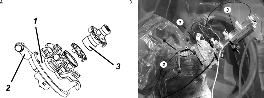
STarFix Platform
Nexframe
System Verification
Operative Procedure
Related posts:

Stay updated, free articles. Join our Telegram channel

Full access? Get Clinical Tree


