Fig. 2.1
Coupling phenomenon i.e. axial rotation of the spinous processes away from the concave side of the direction of the lateral bending. Arrows just above the head show the lateral bending on the left and right, while the ring arrow and black arrows suggest contralateral rotation of the spinous processes of the lower cervical spine (From White and Panjabi Ref. [37], with permission)
The IAR can be considered similar to the COR (centre of rotation), first described by Penning [4] and more recently applied by Smith [5]. This method describes the motion behavior of the vertebral body respect to the adjacent one, defining the axis and the point about which vertebrae rotate. IAR or COR should be considered dynamic because nearly any motion of the FSU is a coupled motion. As spinal movement occurs, infact, the point about which adjacent vertebrae rotate varies during the motion. An extension of the COR approach provides an helical axis of motion (HAM) that defines a three-dimensional movement when rotation is superimposed on translation. The resultant component of motion is described by the translational movement vector called HAM.
Summary of Biomechanical Terms
Translation
Motion of a rigid body in which each straight line through any pair of its points remains parallel to itself
Rotation
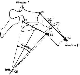
Motion of a rigid body in which each straight line does not remain parallel but develops an angle of rotation between initial position (A1–B1) and final position (A2–B2) (Fig. 2.2).


Fig. 2.2
Vertebral motion , defined by translation vectors A1–A2 and B1–B2, is a rotation about the instantaneous axis (IAR). IAR is obtained by the intersection of the lines perpendicular to the motion plane and the translational vectors (From Panjabi et al. [1], with permission)
Centre of Rotation or instantaneous axis of rotation (IAR)
It is a fixed point obtained by the intersection of the line perpendicular to the motion plane and the translational vector (e.g. A1–A2 see Fig. 2.2)
Degrees of freedom
They define the position of an object in the space by a number of independent coordinates organized in a coordinate system (i.e. Cartesian system)
Range of motion (ROM)
Extent of physiological movement, measured from a neutral position of the spine, when the internal stresses and the musculature effort to hold the posture are minimal. Physiological ROM can be divided into two parts: neutral zone and elastic zone
Neutral zone (NZ)
First part of ROM within which displacement of a biological tissue is produced against minimal internal resistance. The NZ is defined by flexibility of the tissue.
Elastic zone (EZ)
That part of ROM, measured from the end of the NZ up to the elastic limit, in which displacement is produced against internal resistance. The EZ represents the stiffness of the biological tissue
Plastic zone (PZ)
It is the zone of trauma and failure of the biological tissue. When the elastic limit is reached, permanent deformation/displacement can occur. The tissue will fail if further forces are applied
Force
Any action that tends to change the state of rest or motion of a body to which it is applied. Force is a vector quantity that has magnitude and direction. The unit of measure for the magnitude of force is newtons (N).
Work and Energy
Work is the product of force time distance and energy is the work done. The unit of measure is newton-meter (N-m) or joule (J)
Stress
It is the force applied to an object (load)
Strain
It is the response of the object to the stress (deformation)
Viscoelasticity
It is the time-dependent property of a such material to rate of loading or deformation. Bones, ligaments, tendons, passive muscles demonstrate viscoelastic behavior. Because of this, their stress-strain curves are dependent on the rate of loading
Elastic modulus (Young’s modulus)
It is the ratio between stress and strain, representing the elastic properties of a body that is stretched or compressed
Coupling
It is the phenomenon whereby a movement of the spine on a plane obligates a separate motion about another axis (see Fig. 2.1)
Functions of the Cervical Spine
The craniovertebral junction (C0–C1) , the upper (C1–C2) and the lower cervical spine (C3–C7) have distinct anatomic and kinematic features and must be described separately. Fundamental to understanding the behavior of the cervical spine is an appreciation of how each segment contributes to the total function in relation to its specific characteristics. For descriptive purposes, the cervical spine can be divided in five units, each with unique morphology that determines its kinematics and its percentage of contribution to the entire function. In anatomical terms, the units are: the occipito-cervical junction (C0–C1), the atlas (C1), the axis (C2), C2–C3 junction, C3–C7 levels. Main anatomical characteristics of the upper compared to the lower cervical spine include the absence of the intervertebral disc, the absence of the ligamentum flavum, and the distinct shape between C1 and C2.
Occipitoatlantoaxial Complex (C0–C2)
Biomechanically Relevant Anatomy
The foramen magnum (FM) is located in the occipital bone, which has three parts: – the squamosal portion in the dorsal aspect; – the clival portion located anteriorly; the condylar part, connecting these two portions, that includes the occipital condyle, posterior margin of the jugular foramen and the hypoglossal canal. Occypital condyle receives the C1 lateral mass. The most posterior margin of the foramen magnum is called “opisthion”, while the “basion” represents its most anterior midline. C1 differs from the other cervical vertebra by being a ring shape and lacks a vertebral body and a spinous process. It has two thick lateral masses which are situated at the anterolateral part of the ring. C2 has many attributes of the more caudal cervical vertebrae, but its transitional nature dictates a complicated anatomy configuration. Odontoid process represents its rostral extension: this fundamental structure originates by the developmental fusion process between the caudal part of the C1 somite and the cranial part of the C2 somite. The odontoid process begins to fuse with the body of C2 at 4 years of age and at 7 years of age the fusion is completed. In about one-third of adults, a remnant of cartilaginous tissue will be present between the odointoid and the C2 vertebral body. The pars interarticularis projects from the lamina in a rostral and ventral direction to attach to the lateral masses. C1 allows the odontoid process of C2 between its lateral masses. In other terms, odontoid occupies the usual position of the vertebral body [6]. Odontoid articulates with the dorsal aspect of the ventral portion of the C1 arch by an anterior oval facet and posteriorly with the transverse ligament that is attaches to the tubercles on the medial aspect of the C1 ring. The lateral masses of C1 articulate with the occipital condyles and C2 by kidney-shaped articulations, while C2 is directly connected to the occiput by the alar and apical ligaments and the tectorial membrane. In a sense, C1 functions as an intermediate “fulcrum” that regulates movement between the occiput and C2 [7]. The special arrangements of the occipitoatlantoaxial ligaments are remarkable to allow for complex motion, yet provide stability to this area. Infact, the capsules of the C1–C2 lateral facets surround the articular surfaces and are reinforced by ligaments and lateral fibers that pass in a rostral direction from the tectorial membrane [8]. There are ligaments between the C1 anterior arch and the odontoid and behind it: the cruciate ligament that has a vertical component from the rim of the FM to the midportion of the C2 vertebral body; the apical ligament from the rim of the FM to the tip of the odointoid process; the alar ligaments from the lateral anterior rim of the FM to the dorsal aspect of the odontoid. The cruciate ligament is considered one of the most important ligament of the human body and its rupture, identified by high resolution MRI, can lead to craniocervical instability. As stated by Quercioli [9], pioneer of occipito-atlanto-axial biomechanics, the integrity of the transverse and occipitoaxial ligaments is the essential condition for maintaining a stable odontoid process in the axis.
Normal Kinematics
The occipitoatlantoaxial complex is the most mobile of the axial skeleton [10]. This functions as a single unit, considering C1 as a cradle for the occiput and C2 as a washer between the skull and the cervical spine. This complex is responsible for 40 % of total cervical flexion-extension and 60 % of total cervical rotation.
C0–C1 Joint
The atlanto-occipital joint allows flexion-extension and minimal degrees of lateral flexion and rotation, while the atlanto-axial joint works in coupled, rotation plus minimal lateral bending (Table. 2.1). C1 flexion-extension (e.g. nodding movements) are possible because the C1 superior articular surfaces are concave whereas the occipital condyle are convex. Flexion is achieved by the condyles rolling forwards and sliding backwards across the anterior walls of the notches. A converse combination of movements occurs in extension. Axial forces apply by the mass of the head and the muscles prevent upward displacement, maintaining the condyles nestled on the floor of their cavities. The total normal range of flexion-extension at the atlanto-occipital joint has been described as having a mean value between 14 and 35°, a range from 0 to 25° or a mean value of 14° with a standard deviation of 15° [3, 11, 12]. During these movements, a minimal anterior or posterior translation was observed [13]. Moreover, other restraints to flexion are fixed by the impaction against the skull base, tension of the posterior muscles and capsules and contact of the submandibular tissues against the throat. Extension is limited by compression of the suboccipital muscles against the occiput. Rotation and lateral flexion of atlanto-occipital joint are extremely limited, approximately 5°, due to the depth of the atlantal notches in which the occipital condyles rest. In biomechanical terms, during axial rotation to one side, the contralateral occipital condyle contacts the anterior wall of its atlantal notch, while ipsilateral condyle impacts the corresponding atlantal posterior wall. Therefore, joint stability stems largely from the depth of the C1 notches: their side walls prevent lateral translation, the front and back walls prevent anterior and posterior dislocation.
Joint | Motion | ROM (degrees) |
|---|---|---|
C0–C1 | Flexion/extension | 25 |
Lateral bending (unilateral) | 5 | |
Axial rotation (unilateral) | 5 | |
C1–C2 | Flexion-extension | 25 |
Lateral bending (unilateral) | 5 | |
Axial rotation (unilateral) | 40 |
The IAR for the C0–C1 articulation has not been defined, although x-axis is considered to pass through the mastoids and the z-axis to be 2–3 mm above the tip of t he odontoid process [14]
C1–C2 Joint
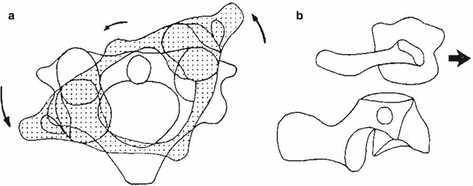
The atlanto-axial complex is composed by two lateral facet joints, the unique atlantodental articulation and the joint between the posterior surface of the odontoid and the transverse ligament. Stability at this highly mobile articulation is primarily dependent on ligamentous structures, because the lateral joint capsules, in contrast to that of the atlantooccipital joint, are loose. Its foremost rule is to bear the axial load of the head and atlas and to transmit this load into the remainder of the cervical spine. For this function, C2 laterally presents wide superior articular facets that support the lateral masses of C1 and form the lateral atlanto-axial joints. The centrally-placed odontoid process acts as the “pivot” and forms the atlanto-axial median joint. In order to achieve axial rotation, the anterior arch of the atlas spins and glides around the pivot. Therefore, this movement is anteriorly restrained by the median atlanto-axial joint and inferiorly by the lateral atlanto-axial joints, that also subluxate. In particular, the ipsilateral lateral mass of C1 slides backwards and medially, while the contralateral lateral mass slides forwards and medially (Fig. 2.3). During axial rotation, the lateral atlanto-axial joints glide across their osseous flat surfaces. But the articular cartilages both of the atlantial and the axial facets are convex in the sagittal plane, rendering the joint biconvex in structure. In addition to these anatomical features, the spaces formed anteriorly and posteriorly by the detachment of the articular surfaces, are filled by large intra-articular meniscoids: these serve to keep a film of synovial fluid on articular surfaces. In the neutral position, the summit of the atlantial convexity rests on the convexity of the axial facet, i.e. the apex of the C1 inferior facets is balanced on the apex of the C2 superior facets. As the C1 rotates, the ipsilateral atlantial facet slides down the posterior slope of the respective axial facet, while the contralateral one slides down the anterior slope of axial facet. Upon reversing the rotation, C1 rises back onto the summit of the facets. In conclusion, C1 axial rotation requires anterior displacement of one lateral mass and a reciprocal posterior displacement of the opposite lateral mass. If the articular cartilages are asymmetrical, a small amplitude of lateral bending may accompany axial rotation: the side of coupling depends on the bias of asymmetry [15], but however this movement is considered negligible [16]1. Principal structures that restrain axial rotation are the alar ligaments and the joint capsules: at the limits of rotation, the lateral atlanto-axial joints are almost subluxated. The normal ranges of rotation of C1 on C2 are varied (see Table 2.1): 32° e 56.7 in cadaveric studies [17a, 18], over 75° using x-ray [19] and 43° using CT [17b] in healthy adults. Recently, some authors [20], measuring in vivo by MRI normal kinematics of the upper cervical spine in neutral position and during Dvorak’s flexio-rotation test, reported respectively 77.6° and 65° of C1–C2 segmental rotation. Sagittal plane motion (flexion-extension) in C1–C2 has been reported by several authors to be on average of 11° and may be facilitated by the rounded tip of the odontoid process [21–23]. More recently, this value has been confirmed by a descriptive study based on computer-aided measurements from lateral flexion-extension radiographs [24]. The biconvex nature of the atlanto-axial articulation means that cervical spine flexion and extension often create motion in the direction opposite that being experienced in the atlas [25]. In other terms, when the entire cervical spine is flexing, C1 extends and when the cervical spine extends, C1 flexes. This paradoxical coupling motion is possible because C1 is sandwiched between the head and C2, undergoing a passive movement. Infact, in neutral condition, C1 is balanced precariously on the convexities of its articular cartilages, but when an axial compression load is applied, C1 starts to move. If the line of compression is anterior to the balance point, C1 moves into flexion. On the contrary, when the line is posterior, C1 will extend. This paradox is governed essentially by the muscles acting on the head and it can be observed even if the rest of the cervical spine is flexed. The restraint to C1 flexion/extension have never been formally established. No ligaments are disposed to limit this motion: essentially C1 is free to flex or extend until the posterior arch hits the occiput or the neural arch of C2, respectively. C1 backward sliding is limited by the impaction of its anterior arch against the odontoid process, while forward slipping is prevented by the transverse and the alar ligaments. Subluxation or dislocation implies destruction of both ligaments. Up to 3 mm of anterior translation of C1 on C2, as measured by anterior atlantodental interval (AADI), is considered normal. As the AADI increases to 5 mm or greater, the transverse and accessory ligaments are disrupted. When the transverse ligament is damaged, also rotary dislocation can occur at 45° of rotation, rather than 65° in normal condition.


Fig. 2.3
C1–C2 axial rotation. (a) (axial view): the anterior arch of C1 glides around the odontoid process (arrows); (b) (sagittal view): the lateral mass of C1 subluxates (arrow) forwards across the superior articular process of C2 (From Bogduk and Mercer [13], with permission)
The IAR for the C1–C2 sagittal plane motion is located in the region of the middle third of the odontoid. During axial rotation, it is located in the centre of the odontoid.
C2–C3 Junction or Vertebroaxial Joint [26]
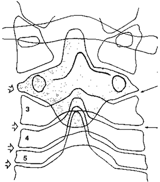
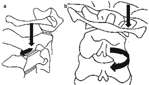
Although the C2–C3 junction is often considered together with the rest of the lower cervical spine, this joint offers some peculiar differences in morphology. A pillar view of the region2 reveals that the body of the axis looks like a deep “root” into the typical cervical spine (Fig. 2.4), securing the upper cervical spine in the remaining cervical column. Moreover, in such view, the unique orientation of the C2–C3 zygoaphophysial joints is seen: they are inclined medially, by about 40° [26], and downward [27], while they are typically transversal at lower levels. The processes of both sides form a notch, cradling the inferior articular processes of the axis. This architecture implies that C2–C3 joints operate in a different manner from that of lower cervical segments, nevertheless further differences are open to discovery. The main kinematic expression occurs during axial rotation plus lateral bending. According to Mimura et al [19], C2–C3 axial rotation is similar to that of the lower segments, with mean value of 7° compared to 5, whereas lateral flexion is significantly different, with mean value of −2° at C2–C3 compared to 6 at C3–C4 and C4–C5 levels. In other terms, instead of tilting towards the same side, C2–C3 joint rotates towards the direction of the side bending (Fig. 2.5). The IAR for the C2–C3 sagittal motion is located lower than in the other cervical levels due to the lower location of the superior articular process of C3 (see below Fig. 2.7).


Fig. 2.4
Pillar view of the upper cervical spine, showing the unique morphology of C2 and architecture of the C2–C3 joints (see text). All arrows indicate the orientation of the interarticular space for each level (From Bogduk and Mercer [13], with permission)

Fig. 2.5
Axial compression force is applied during lateral bending of the head (Vertical black arrows); (a) (sagittal view): the inferior articular process of C2 slides downward and backword along the superior articular process of C3 (Black oblique arrow); (b) (coronal view): C2 rotates towards the direction of the side bending due to the backward articular displacement (ring arrow)
Mid and Lower Cervical Spine (C3–C7)
Biomechanically Relevant Anatomy and Kinematics
The middle and lower cervical spine segments have essential similar anatomic and functional features and can be effectively represented by the FSU: two vertebral bodies, the disc, the facet joints with associated ligamentous and capsular structures. Each vertebra consists of 3 pillars that forms 3 parallel columns for the load-bearing functions of the cervical spine. The anterior pillar is the vertebral bodies, which are united by interposed discs to form the anterior column. The two posterior columns are formed by the articular pillars: the superior and inferior facets are opposed to one another and united by a joint capsules. Their specific orientations allow to bear the weight of the segments above and prevent dislocation. The facet joints are the principal restraints against forward translation. End-plates of the vertebral bodies, that are stacked on one another, separated by the intervertebral disc, are not flat as in the lumbar spine. In the sagittal plane , they appear gently curved, tilting greatly downwards and forwards. The anterior inferior border of each vertebral body forms a lip that hangs, like an hook, towards the anterior superior edge of the vertebra below. As a result, the plane of intervertebral disc is not perpendicular but somewhat oblique and supports flexion-extension motion as cardinal movement of these typical cervical segments. The body supplies the strength and support for two-thirds of the vertebral compression load. The upper surface is typically concave from side to side and convex in the antero-posterior direction. On its lower surface, it is convex from side to side and concave in the antero-posterior direction. Also, the upper projection on the lateral superior surface of the vertebra below is called “the uncus” . These bilateral uncinate processes are related intimately with the convex lateral inferior surfaces of the upper vertebral body and form the uncovertebral joints or joints of Luschka. The exact rule of these joints is not known: they would seem to prevent posterior dislocation and limit lateral bending.
Stay updated, free articles. Join our Telegram channel

Full access? Get Clinical Tree


