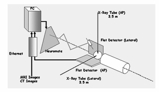
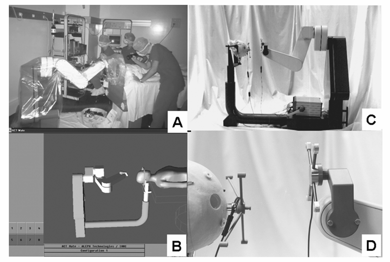
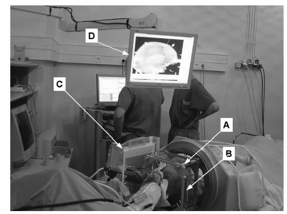
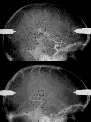
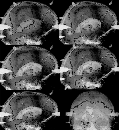
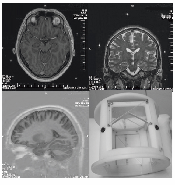
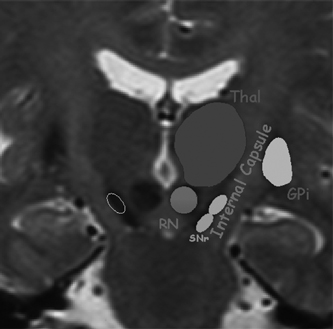
9 Implantation of Multiple Electrodes and Robotic Techniques Alim Louis Benabid, Bradley Wallace, Dominique Hoffmann, Stephan Chabardes, Sylvie Grand, and Jean François LeBas Advances in stereotactic methods, which are typically variations of the same basic design, entail modifications offering improved accuracy and speed while maintaining the quality of the operation. Various prototypes of robots developed during the past 10 years have permitted the fulfilment of this goal. This chapter describes the use of the NeuroMate robotic arm (Schaerer-Mayfield, Lyon, France), which has been developed in our department over the past 15 years and is currently used for all stereotactic procedures performed at our institution. The chapter also deals with the application of this methodology to the stereotactic implantation of intracerebral electrodes, particularly stimulating electrodes to be connected to implantable generators used in the treatment of movement disorders, epilepsy, obsessive—compulsive disorders, and emerging applications such as cluster headache and obesity, as well as depth recording electrodes for electroencephalography (EEG) used in the evaluation of pharmacoresistant epilepsies before the planning of resective surgery. The chapter describes the procedures, advantages, and drawbacks of robotic surgery compared with classic, frame-based surgery. The current version of the NeuroMate robotic arm (Schaerer-Mayfield, Lyon, France), which is discussed in this chapter, is the third prototype of the system, in development since 19891,2 and used by other teams.3,4 It is made up of three components (Fig. 9.1): the robotic arm, the computer housing the software and data files, and the stereotactic frame. The NeuroMate robotic arm (Fig. 9.2) is available in two versions. The first is a mobile system that can be stored in a corner of the operating room when not in use and can be accurately repositioned into a dedicated location in the operating room using a pin and plate system mounted into the floor. Our department uses the second version that is permanently fixed to the floor at the intersection of two teleradiological X-ray tubes positioned 3.5 m from the head of the patient to minimize the magnification coefficient. The body of the system houses most of the electronics needed to activate the robot, particularly the computer called the controller. The controller translates commands given by the neuronavigation software into the six axes of the robotic arm. The trajectory to be used is a line defined by two points in space (each defined by three Cartesian coordinates). From this body, a succession of segments is articulated together by mobile joints (Figs. 9.1 and 9.2). The first axis is collinear to the axis of the patient in the supine position on the operating table. The second axis is perpendicular to the first and provides an additional degree of freedom to rotate from one side of the patient to the other. The third axis provides the opportunity for angulations of the rest of the system and consists of two segments of ~50 cm in length that are analogous to an arm and forearm of the robot. At the end of the forearm, an additional perpendicular axis is designed to receive a holding plate, which can also rotate by 360 degrees. This holding plate can be fitted with a tool holder compatible with a series of specific equipment needed to perform the stereotactic procedures. These tools are mainly guide tubes through which penetration of both the skull and the underlying dura can be performed along a preplanned trajectory. Additional equipment can be mounted on this tool, for example, a microdrive to advance the microrecording electrodes into the brain toward the target. The neurosurgeon—machine interface consists of a PC powered by a 400 MHz Pentium 4 microprocessor with 512 MB of RAM, and a 40 GB hard drive. The PC is connected to the controller of the robot on one side, and on the other receives data through a digitizing scanner, or more commonly through a local area network (LAN) connection to an Ethernet network allowing the transfer of images such as a magnetic resonance imaging (MRI) study coming from the radiology department, or any other kind of digital data. This computer houses the neuronavigation software, VoXim [Integrated Visualization Systems (IVS), Chemnitz, Germany]. VoXim version 4.01 is capable of receiving three types of digital imaging data: (1) anteroposterior (AP) and lateral skull X-ray images obtained by the biorthogonal teleradiological tubes. Based on ventriculographic landmarks from these images, the basal ganglia targets [ventral intermediate nucleus (Vim) of the thalamus, globus pallidus interna (GPi), or subthalamic nucleus (STN)] for functional neurosurgery of movement disorders can be defined. Avascular operative windows can be determined from angiographic images for the introduction of depth electrodes for stereoelectroencephalography (SEEG). Trajectory coordinates from these determinations provide the target points and paths for the robot motion. (2) Computed tomographic (CT) scans can also provide these data via transmission through the Ethernet image network. (3) More frequently this would be MRI studies (T1, T2, axial, sagittal, coronal) coming through the Ethernet image network. The neuronavigation tools included in this software will allow the predetermination of the best target, on the basis of statistical data banks, which could be reached by the robot when it comes into position and action. Fig. 9.1 Flow chart of the NeuroMate robotized stereotactic system. (See Color Plate 9.1.) Fig. 9.2 General pictures of the NeuroMate robotized arm, the ultrasound guidance system, and the “flight simulator.” (See Color Plate 9.2.) The third component is the stereotactic frame (Fig. 9.3). Any currently available stereotactic frame can be used to rigidly fix the patient’s head at the intersection of the two X-ray teleradiological beams. Frames typically have fiducial systems for use with angiography, CT, and MRI enabling the imaging data to be stereotactically registered for transfer to the robot. The frame currently used at our institution is a universal stereotactic frame derived from the Talairach frame to which an X-ray localizer, angiographic localizer, or fiducial grids (when orthogonal penetrations, frontal or lateral, are needed without the use of the robot) can be attached. This frame is mounted on a rotating circle, coaxial to the main axis of the patient allowing either partially rotated images to be obtained for stereoscopic angiograms or to place the patient in positions during ventriculography to better visualize the anterior part of the 3rd ventricle, namely the anterior commissure, which is an important stereotactic landmark. Two X-ray tubes are set at a 90 degree angle (Fig. 9.1), one on the operating room wall for lateral views, and the other one on the ceiling for AP views. Both are at a fixed distance of 3.5 m from the X-ray film, creating a magnifcation coefficient of 1.05 (i.e., 5%) for structures in the center of the brain. Fig. 9.3 Stereotactic frame and flat detectors. (A) Stereotactic frame mounted on a rotating solid-state stand. (B) X-ray Plexiglas localizers mounted on the stereotactic frame. (C) Flat angiography digitizers mounted in orthogonal setup with longdistance X-ray generators. (D) Display of X-ray images. (See Color Plate 9.3.) X-ray films have the best spatial resolution, which results from a combination of the film grain (which can be reduced as necessary), and the size of the electron-emitting source on the X-ray tube anode, which has to be small. However, when the source is too small, the flux of electrons, and therefore of X-rays, is limited because of concern about overheating. Fortunately, the teleradiological setup decreases the apparent diameter of the source (as the reciprocal of the distance), which partially compensates for the decrease in X-ray flux (as the reciprocal of the square of the distance) resulting in increased image resolution. However, to be suitable for robotic applications and digital targeting, X-ray films must be digitized through scanning, which is time consuming and decreases quality. Digitized detectors should be much better but common light amplifiers have a strong distortion coefficient, which tends to distort the image of square objects by the so-called cushion deformation, which is extremely difficult to compensate. Recent developments have made available flat digital detectors (Fig. 9.3) that have no planar distortion and retain an acceptable degree of spatial resolution. These flat digitized detectors (Bioscan, Geneva, Switzerland), therefore, have the major advantage of providing digitized radiographic images, which can be available online (saving significant time and expense associated with the processing of X-ray film), are able to be immediately transferred by Ethernet to the neuronavigation software, and can be subjected to image processing (filtering, subtraction, addition, measures, construction of schemes and targets). The structure of the stereotactic setup makes it possible to perform the entire procedure in a single session, or to split it into multiple steps that can be performed at separate times, even on different days, which is typical in the current protocol at our institution. Under general anesthesia, patients are secured to the stereotactic frame using four twist drill perforations of the skull. For implantation of electrodes in the basal ganglia, calvarial screws are inserted into the perforations, which allows for repositioning the frame several days late while retaining submillimetric precision over the subsequent steps (ventriculography, preimplantation MRI, electrode implantation, postimplantation MRI). For SEEG electrodes, surgery is performed relatively later (within several days to several months) requiring transparietal pins that are inserted into 2.3 mm diameter twist drill perforations with the position recorded on the frame vernier scales. Direct carotid puncture is performed with an 18-gauge Teflon catheter, and 6 mL of Vasobrix (Schering, Berlin) are injected using a programmable, pressure-controlled, injector. Seventy-two images are taken and stored in the digital subtraction angiography computer for further treatment, such as subtraction, and trajectory planning. Images are first obtained in orthogonal AP and lateral views (Fig. 9.4), in the supine position, and then again with the head tilted by 5 degrees toward the contralateral side for stereoscopic views and depth determination of the vessels. Freehand puncture of the frontal horn is performed at 9 cm from the nasion, and 2.5 cm from the midline using a 6.5 cm Cushing cannula. Air (0.5 mL) is injected to verify the location of the cannula in the frontal horn, and not in the interhemispheric fissure. Then 6.5 mL of Iopamiron (Schering) is injected over 5 to 10 seconds during which a sequence of 30 images is obtained laterally, immediately followed by AP views (Fig. 9.5). From the lateral sequence, a single image in which all third ventricular landmarks are visible (namely, the anterior and posterior commissures) is selected and target coordinates are calculated and superimposed. Fig. 9.4 Stereotactic angiograms: arteries and veins sampled from a continuous X-ray video sequence. The VoXim software of the NeuroMate allows two MRI acquisition modalities. In both cases, the T1- and T2-weighted MRI sequences are matched by the software, resulting in improved target definition. This is particularly important for implantation of the basal ganglia where the STN is visible only on T2 sequences. In the first acquisition modality (frame-based MRI), a specially designed MRI localizer (Fig. 9.6) is attached to the patient’s head using four titanium pins inserted at the same depth as the stereotactic frame at the time of the X-ray data acquisition. The MRI data can therefore be precisely coregistered with the ventriculographic data, allowing precise targeting based on fusion of these two datasets. The second modality uses a “helicopter” frameless localizer. A base is screwed into the skull just prior to the implantation session (usually the day before surgery). On this base a four-armed localizer is mounted that bears four markers impregnated with MRI-visible gadolinium-DTPA (diethylene-triamine pentaacetate). At the time of surgery, the gadolinium localizer is replaced by a similar second localizer bearing four ultrasound emitters instead of gadolinium. The ultrasound localizer is then recognized by a set of four ultrasound detectors attached to the robotic arm. The VoXim neuronavigation software then positions the robot in front of the ultrasound emitters, allowing coregistration of the robot with the markers, and therefore to the patient’s brain. Fig. 9.5 Four frames taken from a video ventriculographic sequence (four upper images) and deep brain stimulation (DBS) target planning from the anteroposterior and lateral views of the ventriculogram, and planning of the DBS target (two lower images). Functional neurosurgery for movement disorders, particularly for Parkinson disease, utilizes three primary basal ganglia targets including Vim, GPi, and the most recent and most commonly used, STN. These nuclei can be targeted in different ways, including derivation of Cartesian coordinates from atlases, and validated by clinical experience. Target coordinates are based on a referential system, which is centered on an AP axis between the posterior commissure (PC) and the anterior commissure (AC), the midsagittal plane bisecting the third ventricle, and laterality on an axis perpendicular to the midsagittal plane. To minimize the effect of interindividual variations, the AP coordinate is expressed as 12ths of the AC—PC distance (~27 ± 2 mm). The vertical coordinate is normalized against the height of the thalamus (~18 mm ± 2 mm) and is expressed as eighths of this value. The laterality is expressed in millimeters because there is currently no satisfactory internal standard by which it can be normalized. For the thalamic target Vim, Tasker’s rule proposes using a laterality of 11 0.5 mm plus half of the width of the third ventricle. Table 9.1 shows the numerical values of these three target coordinates, derived from our own experience. Another way to determine the position of the target is direct targeting, which involves aiming at the center of the target that is visible on the MRI (Fig. 9.7). Vim is not visible, but its laterality can be determined by the external limit of the thalamus abutting the internal capsule. The GPi is easily visualized on axial images, particularly on inversion recovery spin echo—weighted MRI sequences. The best GPi target point is situated at the most posterior part of the internal pallidum, medial to the external pallidum, and at the bottom of the GPi. The STN is usually well visualized on T2-weighted coronal images, which allow it to be differentiated from the underlying substantia nigra pars reticulata (SNr). The respective values of these various methods remain debatable. Controversy is based mainly on the distortion present in MRI that cannot be easily controlled. Fig. 9.6 Stereotactic magnetic resonance imaging (MRI) and MRI localizer head set. (See Color Plate 9.6.) Once the target has been determined, the path for implantation requires the determination of the entry point. The general direction of the track is provided by the scheme of the theoretical targets, based on Guiot’s diagram (Fig. 9.5). The theoretical entry point is projected to the vicinity of the coronal suture, ~15 to 35 mm from the midline. The trajectory can be intraoperatively verified from the entry point to the target. The software provides a simulation of the probe, depending on the system used. At our institution, five parallel guide tubes are introduced, separated by 2 mm from center to center, creating a global diameter of 6 mms. The entry point can be modified as needed to allow a safe penetration of the guide tubes and avoid the arteries and veins on the surface of the cortex or penetrating the F1—F2 sulcus. At greater depths, care should be taken to avoid the caudate nucleus because bilateral lesions may be responsible for postoperative confusion. The ventricle should also be avoided, when possible, because its penetration might result in bleeding from subependymal veins and possible deviation of the electrode during final implantation.
Materials
Robotic Arm
Computer
Stereotactic Frame
X-ray Intraoperative Setup
X-ray Tubes in Teleradiological Setup
Flat Digitized Detectors
Method
Acquisition of Image Data
Application of the Frame and X-ray Acquisition
Angiography
Ventriculography
MRI
Planning of Electrode Implantation

Stay updated, free articles. Join our Telegram channel

Full access? Get Clinical Tree


