Chapter 175 Intraoperative Imaging
Plain Film Radiography
Even when the correct level is identified, localization errors may occur. For example, localization in the lumbar spine typically involves placing a marker on a spinous process and obtaining a lateral radiograph. Although the correct spinous process may be visualized on the film, continued surgical dissection down to the level of the lumbar canal may cause the surgeon to easily drift to an adjacent lumbar segment above or below the desired level. Placement of a marker at the level of the lumbar lamina in addition to the marker on the spinous process can help prevent this error.
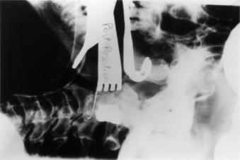
In addition to localization of the spinal level, plain radiography can be used in isolated instances to assess the extent of neural decompression. This technique is particularly useful during transoral decompressive procedures. It involves placing a radiopaque contrast medium into the decompressed site and obtaining a lateral radiograph. The radiograph will show the extent of the decompression and can be compared with a preoperative study demonstrating the neural compression. If the configuration and location of the contained contrast medium does not approximate the configuration and location of the epidural compression on the preoperative studies, the surgical site can be modified until a satisfactory decompression of the neural elements is achieved (Fig. 175-1).
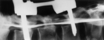
Plain radiography can also be used in conjunction with intraoperative myelography to determine the extent of canal decompression.1 In the setting of a thoracolumbar burst fracture decompressed through a dorsolateral approach, radiopaque dye can be placed in the subarachnoid space by a small-gauge spinal needle to assess the adequacy of the surgical decompression. A lateral radiograph is taken and the relationship of the dye to the ventral spinal cord can be assessed (Fig. 175-2).
Fluoroscopy
Fluoroscopy is used when real-time imaging or multiple images of the spine are required during surgery. Fluoroscopic images are generated with a lower radiation dose than that for standard radiography. A camera records the image and displays it on a television monitor. The images can be recorded on x-ray film, cinefluoradiography film, or videotape.2
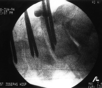
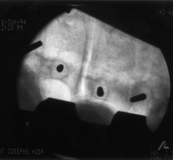
The primary use of fluoroscopy in spine surgery is to facilitate the optimal placement and positioning of spine fixation screws, interbody cages, or arthroplasty devices and to monitor the injection of methyl methacrylate into osteoporotic vertebral body fractures. Fluoroscopy can provide the surgeon with real-time imaging of the spinal column in several planes depending on the positioning of the fluoroscope’s C-arm. When used for the insertion of pedicle screws, the C-arm can be positioned to provide a lateral view of the spinal column. This shows the sagittal (rostrocaudal) orientation of a pedicle marker or screw (Fig. 175-3). By rotating the C-arm from the lateral position toward the AP position, an oblique view of the spinal column can be obtained. This view demonstrates the position of a pedicle marker or screw in relationship to a cross-sectional view of each pedicle. If the correct entry point and trajectory in both the sagittal and axial planes has been properly selected, the oblique fluoroscopic view will demonstrate these markers within the cortical margins of the individual pedicles (Fig. 175-4). When the correct entry point and trajectories have been confirmed, the markers can be removed and the pedicle screws inserted along the same path.
When used for cervical screw fixation (e.g., ventral odontoid screw fixation), an AP as well as a lateral view may be required. This can be obtained by alternating the position of a single C-arm unit from the lateral to the AP position or by using two separate fluoroscopy machines with arms positioned 90 degrees with respect to each other.3
Fluoroscopy has also been used for ventral cervical plate instrumentation procedures to assist in the positioning and placement of the fixation plates and screws.4 However, the lower cervical and upper thoracic regions can frequently be difficult to visualize because of image obstruction by the patient’s shoulders. This problem can be addressed by placing an interscapular roll beneath the patient and taping the shoulders down to the table or by using wrist slings to pull down on the patient’s arms during imaging.
The primary disadvantage of intraoperative fluoroscopy is the exposure of the surgical team to repeated amounts of low-dose ionizing radiation. Several studies have attempted to quantify the amount of occupational radiation exposure to health-care professionals under different and real clinical scenarios.5–9 These studies have typically demonstrated that the radiation exposure to hands, eyes, head and neck, and body during fluoroscopically assisted procedures is well below the recommended values for annual allowable occupational radiation exposure as outlined by the International Commission on Radiological Protection.10 However, the health-related risks of this chronic exposure to radiation remains relatively unknown and may not be realized for years.
Unlike other fluoroscopically assisted musculoskeletal procedures (e.g., intramedullary femoral nailing), the techniques and instruments used for pedicle fixation bring the surgeon’s hands very close to the primary area of exposure.11,12 The amount of radiation exposure needed to achieve adequate visualization of the lumbar spine is greater than that for other anatomic sites.13 Rampersaud et al. reported on the radiation exposure occurring during the placement of thoracolumbar pedicle screws.14 Pedicle screws were placed into six cadaver specimens using fluoroscopy. Dosimeter badges and rings were placed on the surgeon’s neck, torso, and dominant hand. Radiation exposure to these sites was quantified.
Ninety-six pedicle screws were placed with an average of 8.5 fluoroscopic images taken per screw. The average exposure time per screw was 9.3 seconds. The results of this study demonstrated that fluoroscopically assisted pedicle screw fixation exposes the spine surgeon to significantly greater radiation levels than other, nonspinal musculoskeletal procedures involving the use of fluoroscopy. The radiation exposure to the dominant hand was noted to be as high as 10 to 12 times the amount of hand exposure experienced in other procedures. The greatest level of exposure was noted on the side ipsilateral to the beam source due to backscatter radiation. This study emphasizes the need for appropriate lead shielding, including the use of a thyroid shield and leaded glasses. The use of radiation attenuation gloves resulted in a 33% decrease in dose rate to the hand. Using limited, pulsed-image acquisition and maintaining a safe distance (3–4 feet) from the radiation source also helped reduce the dosage to negligible levels.14 This study confirmed that spine surgeons who regularly use fluoroscopy should monitor their annual radiation dose.
Ultrasonography
The application of ultrasonography to spine surgery was first reported in 1982.15 Like fluoroscopy, ultrasonography provides continuous and real-time imaging. However, unlike fluoroscopy, which only provides images of the bony spinal column, ultrasonography can image the adjacent neural and soft tissue structures as well.
Diagnostic ultrasound scanners consist of a scan head containing transducers that convert electrical energy to mechanical or sound energy. To obtain a sonogram the scan head of the ultrasound probe is placed against a contact surface. A short ultrasonic pulse is generated by the transducers and transmitted into the contact surface. This pulse travels continuously into the medium until it strikes another surface or encounters a change in acoustic impedance. Acoustic impedance, the product of the density of a material and the velocity of the sound wave, depends not only on tissue density but also on the actual composition and internal structure of a tissue substance.16
When the ultrasound pulse strikes a surface, some of the energy is reflected back to the transducer and some of the energy continues forward. Structures that reflect most or all of the ultrasound pulses striking them, specifically air and bone, prevent the imaging of structures behind them. A reflected ultrasonic pulse returns to the scan head and hits the transducer. The shape of the crystal in the transducer is changed, inducing a voltage across it. This voltage is recorded—its amplitude dependent on the strength of the reflection that contacts the transducer face. The location within the tissue from which the reflection came can easily be calculated once the speed of sound in the tissue being scanned and the interval of time between the generation of the impulse and the reception of the reflected wave are known.
Ultrasonography can be used to localize a variety of lesions within the spinal canal. It is effective for localizing and characterizing intramedullary spinal cord tumors as well as intradural and extramedullary tumors. Ultrasonography can be used before opening the dura to visualize the extent of the tumor and to localize specific areas of interest such as a cyst within the tumor. The images guide the opening of the dura and can often direct the surgeon to a particular location to start the myelotomy and exploration.17 When a cystic tumor such as a hemangioma is present, ultrasonography can help identify the specific mural nodule of the tumor.18
Edema proximal or distal to the tumor also causes widening of the cord seen on ultrasonography and can create confusion in determining the absolute limits of the tumor. However, in most cases, the tumor border is well defined and the edema is less echogenic than the tumor.19
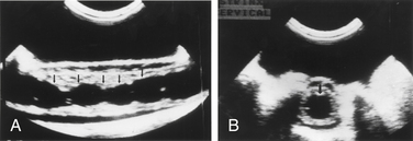
In the setting of syringomyelia, ultrasonography can be used to localize the maximal extent of the syrinx as well as to identify any small septae present (Fig. 175-5).18 If a drainage catheter is placed into the syrinx, ultrasonography can be used to assess the degree of collapse of the cavity and determine whether additional catheters are needed.


Stay updated, free articles. Join our Telegram channel

Full access? Get Clinical Tree


