Fig. 21.1
Different endoscopic approaches to the spine: 1, endoscopically assisted transforaminal lumbar interbody fusion (ETLIF); 2, endoscopic lateral lumbar interbody fusion (ELLIF); 3, laparoscopic anterior lumbar interbody fusion (LALIF); 4, percutaneous endoscopic lumbar interbody fusion (PELIF)
21.2 ETLIF
In 1952 Cloward described the posterior lumbar interbody fusion procedure (PLIF) [7], and later Harms and Rolinger introduced the transforaminal lumbar interbody fusion (TLIF) in 1982 for the management of degenerative spinal disorders that necessitate interbody fusions [8]. TLIF has the advantage of less neural retraction in comparison to PLIF during the cage insertion [9]. Moreover there is no need to expose the epidural space bilaterally [10]. ETLIF combines the advantages of TLIF with a minimal access exposure. The inherent muscle damage from subperiosteal dissections and retraction that have been demonstrated objectively through several studies is believed to adversely affect clinical outcomes [11–15]. ETLIF decreases muscle damage by splitting the muscles fibers without cutting or significantly retracting them. Tubular retractors with the assistance of an endoscope view can provide a minimally invasive exposure. There is no need for a microscope once it is possible to see clearly the neuro structures and even inside the disc space in order to check the adequate endplate preparation. Moreover, the microscope has a propensity for contamination because of unknown contact with unsterile parts of the surgeon, and it can be a source of infection [16].
21.2.1 Indications: Special Considerations
ETLIF is specially indicated in case of unilateral foraminal stenosis. This allows direct foraminal decompression. If bilateral foraminal decompression is needed, a bilateral approach for adequate decompression should be used [17–19]. It’s also a particularly useful approach because there is no need for an access surgeon.
21.2.2 Surgical Technique
After a carefully preoperative planning and evaluation, the patient is brought to the operation room. Somatosensory evoked potential (SSEP) can be used to increase the safety of the procedure in special cases. Patient is prone positioned and care is made to insure adequate padding of all pressure points. The surgeon should stand on the same side of the approach that usually corresponds to the most symptomatic side. In case there is no difference between sides, a right-handed surgeon should stay on the patients left side. Fluoroscopy is used to confirm the level. The 2.5-cm incision is placed 3–4 cm from the midline, and it goes from the superior pedicle to the inferior pedicle centered on the disc space. A Steinmann is placed vertically under lateral fluoroscopy toward the facet complex over the pathological disc space. After confirming the correct positioning, serial soft tissue dilators are introduced (METRx; Medtronic Sofamor Danek, Memphis, TN). For ETLIF a 20-mm or larger working channel is needed.
A monopolar cautery is used to dissect the soft tissue and expose the lamina, isthmus, and facet joint (Fig. 21.2a).
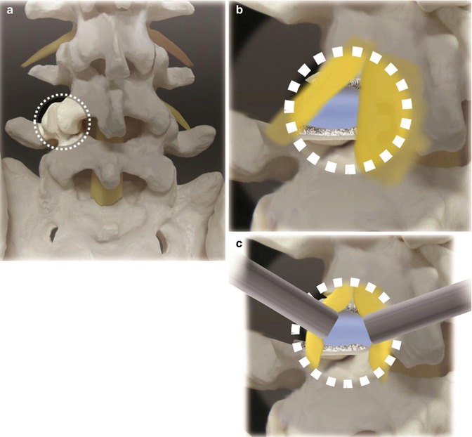

Fig. 21.2
(a) The working channel should be centered on the facet joint with the disc space beneath it. It is important to see the medical facet, lateral interlaminar window, and lama. (b) After removing the facet joint and some lamina, the disc, exiting and traversing root, is exposed. (c) Gently retracting and protecting the neuro structures, we can access the disc and proceed with the discectomy
It is safer to begin laterally where bone is apparent. To maximize the working space is essential to remove all the soft tissue overhanging the anatomic structures. If the medial facet, lateral interlaminar window, and lamina are not clearly seen, the working channel should be repositioned.
Next step consists in a generous hemilaminectomy and facetectomy to expose the lateral aspect of the dural sac and the superior and inferior nerve roots (Fig. 21.2b).
The endoscope magnifies the view. Surgeon hands may obstruct the vision when working in small fields like tubular retractors with a microscope. Endoscopic vision eliminates this drawback. High-speed drills, osteotomes, and Kerrison punches are used. The bone removed and spared is later used as autograft in the interbody fusion. After visualization of the nerve roots, the exiting nerve root is protected or gently retracted laterally. Dural sac and traversing nerve are gently retracted medially to expose the disc space (Fig. 21.2c).
Epidural veins overlaying the disc space may be cauterized with a bipolar cautery. At this moment discectomy is done with a scalpel no.15. The disc material and endplate preparation is done with curettes, pituitary rongeurs, reamers, and plate scrapers using standard technique. The cage’s size is measured in preoperative exams and confirmed using a trial. Disc space is then partially filled with graft. We usually use allograft mixed with autograft collected from the laminotomy site. The cage is also filled up with this mixture of grafts. Chisel is then used to create space for the cage insertion. Endoscopic view allows a better visualization and increases the safety during these steps (Fig. 21.3).
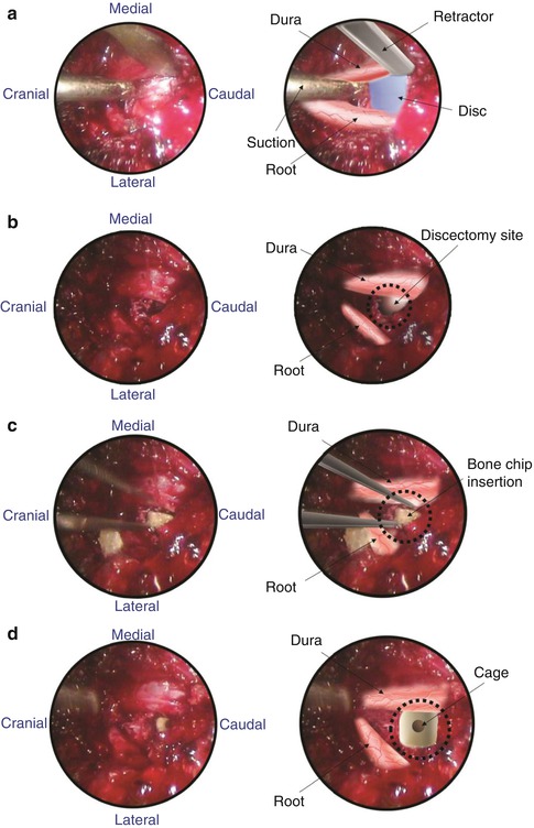

Fig. 21.3
Endoscopic images. (a) Exposure. (b) Discectomy. (c) Bone chip insertion. (d) Cage insertion
Fluoroscopic view is used in the lateral position to confirm the appropriate cage depth. At this step the working channel should be angled to the opposite side. This allows a better angle for the cage placement (Fig. 21.4).
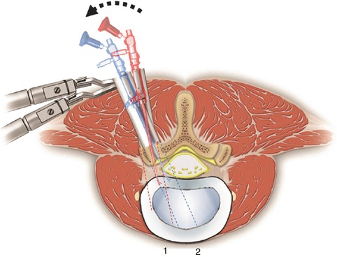

Fig. 21.4
After preparing the endplate, the retractor and endoscope are angled. We should see bleeding endplates without breakage. The endoscope is removed and the cage is inserted
After the cage insertion, the pedicle screws are inserted percutaneously. Insertion of pedicle screws through a midline approach requires massive retraction of the multifidus muscle, subjecting the muscle to high retraction pressures and disruption of its osseo-tendinous attachments and neurovascular supply [14]. Percutaneous screws avoid such muscular injuries. The working channel and endoscope are removed and the procedure is done using the C-arm.
The percutaneous pedicle screw technique begins with a Jamshidi-type trocar needle that is placed under fluoroscopic control through the previous incision. In the opposite site, the screws are placed through separate incisions. A true anteroposterior view with the spinous process centered between each pedicle and a flat superior endplate of the corresponding vertebra and a lateral view with the pedicles and endplate parallels are essential. This can avoid inadvertent malpositioning of the screws. Once the needles are correctly positioned inside the pedicle, the stylets are removed and guide wires inserted (Fig. 21.5).
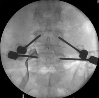

Fig. 21.5
Percutaneous placement of Jamshidi needles through the pedicle. Needle stylets are replaced by guide wires. The needles are removed and taps create the pathway for the screws
The guide wire is then used to direct cannulated taps and screws into the pedicle. C-arm lateral view is important to ensure that the K wire is not advancing. Once the pedicle screws are positioned, the rods are placed percutaneously and then connected. We change the patient’s position into lordosis to avoid a “flat back” before fixing the rods. C-arm is used in lateral view and then in AP view to confirm the appropriate implants positioning (Fig. 21.6).
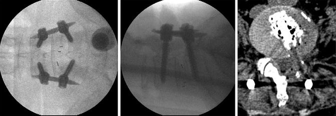

Fig. 21.6
After ETLIF posterior percutaneous screws are inserted. C-arm intraoperatively confirms the good positioning of the implants. Postoperative CT shows good positioning of the cage and bone graft around it
The wound is irrigated, hemostasis is confirmed, and the fascia and skin are closed in a layered fashion. A subfascial drain might be placed for 24 h.
21.3 LALIF
Laparoscopic lumbar discectomy was described in 1991 by Obenchain [20]. The technique was then modified to allow anterior fusion and posterior instrumentation. The use of an anterior approach preserves the posterior muscles and avoids related complications. Moreover, the cages can be bigger when compared to posterior and posterolateral approaches. In addition the laparoscopic approach allows good visualization, decreases the blood loss, and has excellent cosmetic results. However anterior approaches have potential injury to large vessels and retrograde ejaculation as their main drawbacks, and LALIF requires long learning curve [21].
Due to the vascular anatomy at the L4–5 disc level where the large abdominal vessels bifurcate and override the disc space, the technical feasibility differs significantly between L4–5 and L5–S1 levels.
For L5–S1 LALIF have good results quite similar to mini-open ALIF. Blood loss and hospital stay are decreased, and the clinical outcome is statistically the same [22, 23]. It’s a minimally invasive surgery that preserves the important posterior lumbar muscles. However, operative time was higher in the LALIF group [22, 23], and some studies showed a higher retrograde ejaculation rate when compared to ALIF (5.1 % vs. 2.3 %) but without statistical significance [21].
For the L4–5 level, LALIF doesn’t show the same good results. Due to anatomic considerations, the rate of complications is higher [21]. The incidence of retrograde ejaculation is over 10 % [21], and some studies report a conversion to an open procedure in 67 % [24].
No conclusion regarding either the superiority or inferiority of LALIF to the open or mini-open ALIF can be drawn, because of the lack of data with a high level of evidence [21]. However, some spine surgeons are abandoning this procedure and switching to the mini-open ALIF. On the other hand, Beutler et al. published a description of LALIF using the da Vinci Robotic Surgical System for anterior lumbar interbody fusion [25]. He considered the visualization inside the disc space and surrounding structures better than current open and laparoscopic techniques. The future role of LALIF still remains to be followed closely.
21.3.1 Indications: Special Considerations
LALIF is indicated as a stand-alone procedure for patients with DDD, low-grade spondylolisthesis, and post-laminectomy syndrome. A stand-alone LALIF fully preserves posterior muscles and decreases postoperative pain related to dissection. If needed, posterior percutaneous screws increase the stability and may be added. Special considerations must be done for male patients, L4–5 level, and previous abdominal surgery. Those are not formal contraindications but may increase the complications.
21.3.2 Surgical Technique
Here we describe the technique for L5–S1 LALIF. The patient is placed supine on a radiolucent table, and straps are placed on the patient’s ankles to prevent sliding because a steep Trendelenburg’s position is required during the procedure. This allows the abdominal viscera to move cranially out of the pelvis (Fig. 21.7).
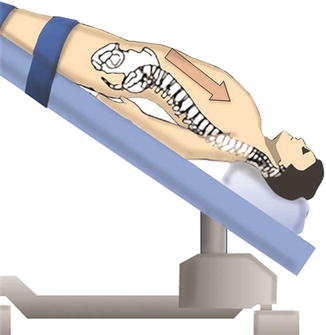

Fig. 21.7
A steep Trendelenburg’s position allows the abdominal content to move cranially out of the pelvis. The patient’s arms are placed under the lumbosacral spine to allow good visualization of the spine under C-arm. A pillow is placed under the knees to prevent hyperextension
Equipment in the room is positioned to allow the surgeon an adequate view of both the C-arm image and the video monitor. Pillows are placed under the patient’s hips to accentuate lumbar lordosis at the lumbosacral junction. It’s also important to prevent knees hyperextension by placing a pillow under them. The arms are placed at the patient’s side, low enough to prevent interference with the fluoroscopic lateral view (Fig. 21.7). A nasogastric tube and Foley catheter are used to decompress the stomach and bladder, respectively. Both catheters are removed at the end of the procedure. Patients are advised that an open laparotomy may be needed in case of uncontrolled bleeding or poor visualization of the lumbar spine, in addition to other potential complications.
The fluoroscopic equipment is then brought into place before the incisions are made to verify the midline. It is important to obtain adequate fluoroscopic views for proper intraoperative visualization of the vertebral bodies and to estimate instruments trajectory. Four incisions are used. The two lower paramedian incisions allow placement of portals for the working forceps (Fig. 21.8).
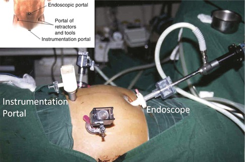

Fig. 21.8
Four routinely incisions. Two paramedian incisions provide conduits for the working forceps. The viewing camera is placed through an umbilical incision. The working channel is placed through a midline suprapubic incision measuring 2–4 cm in length
The incision for the interbody channel and devices is centered over the midline suprapubic region and measures 2–4 cm in length. The viewing camera is placed through the curvilinear umbilical incision.
Stay updated, free articles. Join our Telegram channel

Full access? Get Clinical Tree


