, Maurice M. Smith1 and Y. Raja Rampersaud2
(1)
University of Tennessee Health Science Center, Memphis, TN, USA
(2)
Division of Orthopedic Surgery, Department of Surgery, University of Toronto, Toronto, ON, Canada
Paramedian Approach
1.
Microendoscopic discectomy (MED) can be performed under local, regional, or general anesthesia. Epidural anesthesia is preferred, because it is more comfortable for the patient than local anesthesia and avoids the side effects of general anesthesia. The anesthesiologist should place the epidural catheter while the patient is in the preoperative holding area. The catheter should be inserted in an upper lumbar or lower thoracic interspace well away from the operative field.
2.
In the operating room, place the anesthetized patient in the prone position with abdomen free and spine flexed to open the interlaminar space. Position a C-arm fluoroscope to obtain lateral fluoroscopic images of the operative interspace. Check these images before prepping and draping the patient to ensure that the operative level can be visualized. A typical operating room setup is pictured in Figure 51.1.
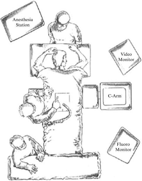

Fig. 51.1
The typical operating room setup for a microendoscopic discectomy (MED). The surgeon is positioned ipsilateral to the disc herniation. The video monitor (contralateral side) is placed in the surgeon’s functional line of sight, and the fluoroscopy monitor is placed toward the foot of the patient
3.
After the operative field has been prepped and draped, attach the flexible arm assembly to the operating table rail ipsilateral to the disc herniation; the arm will hold the tubular retractor/endoscope assembly in position, freeing the surgeon’s hands. Palpate the lumbar midline and mark this line with a surgical pen. Draw a second line parallel to the midline, approximately one fingerbreadth (1.5 cm) to the side of the disc herniation. Insert a 22-gauge spinal needle into the paraspinous tissues along this paramedian line at the approximate level of the appropriate disc space. Under fluoroscopic guidance, reposition the needle until an imaginary line drawn along the needle is parallel to the vertebral endplates and bisects the disc space (Fig. 51.2). At the L5–S1 interspace, where the end plates are typically divergent, the needle trajectory should be parallel to the L5 end plate. Accurate placement of the skin incision directly in line with the final surgical target (e.g., disc space) facilitates optimal use of the space within the tubular retractor; this optimizes the various trajectories attainable by the surgical instrument(s) without having to move the tubular retractor. Adhering to this principle significantly improves the efficiency of this procedure. Withdraw the needle and make a 15-mm longitudinal incision centered at the needle puncture site. Carry the incision into the superficial subcutaneous tissues only (Fig. 51.3).
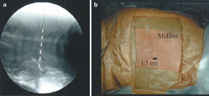
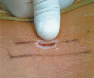

Fig. 51.2
The incision is placed along a paramedian line located 1.5 cm from the midline, ipsilateral to the side of the disc herniation. (a) Using fluoroscopy, the trajectory of a 22-gauge spinal needle should be parallel to the vertebral end plates and bisect the disc space, as illustrated. (b) It is important to ensure that the skin incision is accurately placed in line with the surgical pathology

Fig. 51.3
A 15-mm longitudinal skin incision is made to the depth of the superficial subcutaneous tissue
4.
Insert the 12-inch, 0.062-diameter guidewire through the incision under fluoroscopic guidance. Direct the guidewire toward the inferior edge of the superior lamina. Stop advancing it after the dorsal lumbar fascia has been penetrated (Fig. 51.4).
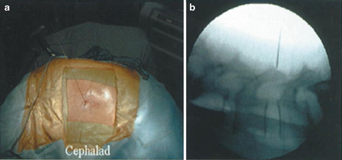

Fig. 51.4
(a) External and (b) fluoroscopic images illustrate placement of the guidewire through the dorsolumbar fascia toward the inferior laminar edge
5.
Insert the cannulated soft tissue dilators over the guidewire and each other (Fig. 51.5). After the first dilator has penetrated the dorsal lumbar fascia, remove the guidewire and advance the dilator until it is docked on the inferior edge of the superior lamina. Confirm the positioning of the dilator in the sagittal plane using lateral fluoroscopy (Fig. 51.6). It is important to obtain a true lateral image to avoid erroneous information from the bony landmarks of the contralateral side. Determine axial plane orientation by palpating the lamina with the tip of the initial dilator; it should lie just lateral to the base of the spinous process and just above the laminar edge.
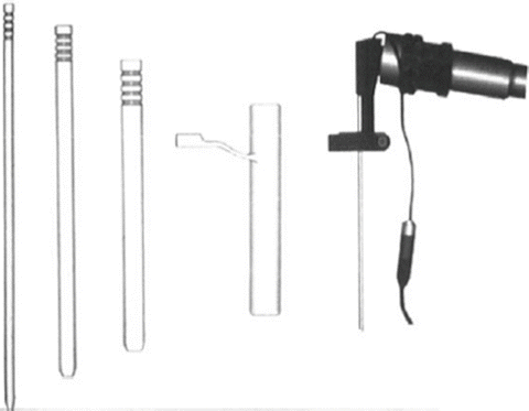
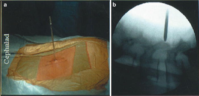

Fig. 51.5
Illustrated from left to right are the three cannulated sequential dilators (5.3 mm, 10 mm, 14.5 mm), the 16-mm tubular retractor, and the 25-degree endoscope

Fig. 51.6
(a) External and (b) fluoroscopic images illustrate docking of the initial dilator tip onto the inferior edge of the superior lamina. Confirmation of this important landmark is easily accomplished by “walking” the tip of a dilator in the caudal direction until the stepoff into the interlaminar space is identified and confirmed fluoroscopically
6.
Use the first dilator to gently dissect the soft tissue from the dorsal aspect of the laminar edge; this allows for easier identification of this important landmark. Place the second and third dilators over the first in a sequential manner, establishing an operative corridor between the fibers of the lumbar paraspinous muscles, but leaving their normal spinal attachments intact (Fig. 51.7).
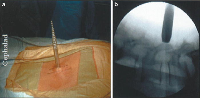

Fig. 51.7
(a) Placement of the sequential dilators with a rotating motion gently dilates the fascia and paraspinal muscles to establish the initial operative corridor to the disc space. (b) Fluoroscopy is used to confirm that each dilator is docked onto bone; this minimizes the amount of soft tissue that can enter into the tubular retractor.
7.
Advance the tubular retractor over the third dilator, down to the lamina. Maintain downward pressure on the dilators so that they remain docked and paraspinous tissue cannot enter the retractor. Connect the tubular retractor to the flexible arm assembly to maintain its position. Confirm the position of the retractor fluoroscopically and remove the dilators (Fig. 51.8).
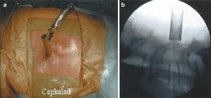

Fig. 51.8
(a) The tubular retractor is centered on the laminar edge. This position is confirmed fluoroscopically (b) and the retractor is locked in place as shown on the left
8.
Connect the endoscope to the coupler and camera, the light source, and a suction tube. White balance the endoscope. Insert the endoscope into the tubular retractor. Secure the endoscope to the retractor using the attached ring clamp. The endoscope can be positioned anywhere within the 360-degree arc of the tubular retractor (Fig. 51.9) and can be advanced or withdrawn within the retractor, allowing for variable magnification (Fig. 51.10). Condensation on the endoscope lens is removed by attaching the aspiration port to suction. Other extraneous matter can be removed from the lens by irrigation or by removing the endoscope, wiping the lens, and reinserting it.
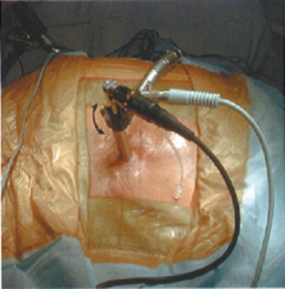
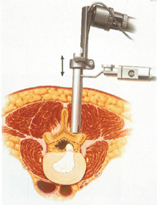

Fig. 51.9
The endoscope is positioned within the retractor and can be rotated 360 degrees around the retractor perimeter. This usage ensures optimal visualization of a given area and allows the surgeon to move the endoscope assembly if it impedes an instrument’s trajectory, without having to move the entire retractor

Fig. 51.10
Magnification of the anatomy is achieved by telescoping (arrow) the endoscope within the tubular retractor
9.
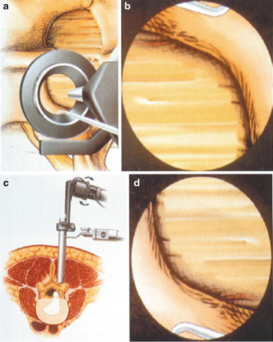
After the endoscope is inserted into the tubular retractor, orient the video image to correspond with the underlying anatomy (Fig. 51.11). Medial anatomy should appear at the top of the video screen (12 o’clock), and lateral anatomy should appear at the bottom (6 o’clock). To achieve proper orientation, place a surgical instrument in a lateral anatomical position within the tubular retractor. Rotate the camera/coupler until the video image shows the instrument at the bottom of the video screen.

