Fig. 5.1
Angle and angle velocity of human hip, knee and ankle in treadmill walking. Hip ankle is calculated between the seventh spine bone, trochanter major and a assumed rotational point at the knee (2 cm above the lateral meniscus at lateral femur condyle). Knee angle is calculated between trochanter major, the rotational point of the knee and the lateral malleolus. Ankle angle is calculated by the rotational point of the knee, the lateral malleolus and the fifth metatarsal joint of the foot. Dots are indicating take off for the individual speeds. Mean values of 21 subjects (25.4 years, 1.73 m, 70.9 kg) (Data from [94])
Fig. 5.3
Joint torque and power for human hip, knee and ankle in treadmill walking. Joint torques are calculated using inverse dynamics. Power is the product of joint velocity and joint torque. Both values are normalized to body mass. Dots are indicating take off for the individual speeds. Mean values of 21 subjects (25.4 years, 1.73 m, 70.9 kg) (Data from [94])
Using a passive prosthetic foot the RoM is about 16.8–21.2∘ for 1.35 m/s walking [125, 165]. 11–23∘ were reported in [63]. Thereby ESAR feet could almost double RoM in comparison to SACH feet that provided only up to 14∘ dorsiflexion. Prosthetic feet with mechanical ankle joint (Lager or 1H38, Otto Bock, [117]) can provide greater ROM than SACH or ESAR feet [125].
For amputees running with a Flex-foot (Ossur, [116]) at 2.7 m/s, a RoM of about 11∘ was achieved [136].
RoM is especially a topic on slopes or stairs. Limitations enforce compensating motion of the other leg joints. In [171] 8∘ ankle RoM was identified for unilateral amputees walking up a slope of 5∘ (SACH foot). The control group had a RoM of about 24∘. Descending the same slope the amputees had an ankle RoM of about 9∘, while the control group had about 20∘. In addition ankle angle at touch down differs significant between the control and the amputee group.
The lag for amputee ankle joint RoM is caused by rigid prosthetic foot mechanisms. Softer mechanisms like ESAR feet could improve performance and may also increase stride length of the residual limb [63]. On the other hand the plantarflexion of a prosthetic ankle during push off is limited to the ankle rest position. Further changes in the ankle angle could only be realized by energy injecting systems. For realizing this in a passive device energy has to be stored first in another phase of the gait cycle.
In a novel semi-passive ankle prototype (Energy Recycling Foot, [21]) energy storage is realized during heel contact. Afterwards it is used to support push off. For push off in walking at preferred speed [28] between 0.2 and 0.29 J/kg of positive ankle work is required (Table 5.1). For a 75 kg person this would be about 15–22 J. In [184] the system returned about 19–25 J in unilateral amputees. The Energy Recycling Foot could double push of energy in comparison to a conventional prosthetic foot. Also net rate of metabolic consumption could be reduced from 23 % above normal (conventional prosthesis) to 14 % (Energy Recycling Foot) using a prosthetic simulator [21]. But more push off work not necessarily results in better gait performance. In [184] it was shown that with the same device softer spring stiffness values could improve positive push off work. This outcome was different to the results for the metabolic rate. It was best for a medium stiffness condition. As reasons excessive heel displacement and center of mass (CoM) collision losses were assumed.
Table 5.1
Positive and negative peak power (W/kg) and work (J/kg) at the ankle joint during walking and running
Gait | Walking | Running | ||||||||||
|---|---|---|---|---|---|---|---|---|---|---|---|---|
Speed (m/s) | 0.5 | 1.1 | 1.6 | 2.1 | 2.6 | 0.5 | 1.1 | 1.6 | 2.1 | 2.6 | 3.0 | 4.0 |
Positive peak power | 0.9 | 2.0 | 3.2 | 4.3 | 4.6 | 5.3 | 6.0 | 6.1 | 7.1 | 8.7 | 10.0 | 14.1 |
Negative peak power | 0.5 | 0.4 | 0.4 | 0.5 | 0.8 | 4.8 | 4.3 | 3.6 | 3.7 | 4.4 | 5.1 | 7.0 |
Positive work | 0.12 | 0.20 | 0.29 | 0.45 | 0.54 | 0.54 | 0.60 | 0.60 | 0.64 | 0.70 | 0.80 | 0.98 |
Negative work | 0.14 | 0.13 | 0.07 | 0.04 | 0.05 | 0.48 | 0.42 | 0.31 | 0.27 | 0.29 | 0.32 | 0.39 |
Table 5.2
Energy, efficiency and peak power values for different passive prosthetic feet in transtibial (TT) and transfemoral (TF) amputees for walking (W ) and running (R). For authors marked with ∗ energy and peak power values are estimated from published figures. Various studies used self-selected preferred walking speed (PWS)
Energy | Peak power | |||||
|---|---|---|---|---|---|---|
absorbed/ | absorbed/ | Gait/ | Subjects/ | |||
returned | Efficiency | returned | speed | level of | ||
Article | Prosthesis | (J/kg) | (%) | (W/kg) | (m/s) | amputation |
Czerniecki | Flex Foot | 0.45/0.38 | 84 | 6.7/5.5 | R/2.8 | 5× TT |
1991 [27] | Seattle Foot | 0.49/0.25 | 52 | 8.2/4.1 | ||
SACH Foot | 0.26/0.08 | 31 | 5.3/1.5 | |||
Gitter ∗ | Flex Foot | 0.29/0.26 | 89 | 1.4/3.6 | W/1.5 | 5× TT |
1991 [53] | Seattle Foot | 0.15/0.11 | 71 | 0.8/1.6 | ||
SACH Foot | 0.1/0.04 | 39 | 0.5/0.7 | |||
Seroussi ∗ | Seattle Light Foot | 0.09/0.07 | 75 | 0.39/0.6 | W/PWS | 8× TF |
1996 [144] | Mauch SNS Knee | |||||
Silverman ∗ | SACH or ESAR | 0.11/0.05 | 45 | 0.3/0.23 | W/0.6 | 14× TT |
2008 [148] | Foot | 0.148/0.06 | 41 | 0.48/0.47 | W/0.9 | |
0.149/0.068 | 46 | 0.67/0.63 | W/1.2 | |||
0.152/0.074 | 49 | 0.78/0.72 | W/1.5 | |||
Prince | Golden Foot | 0.27/0.11 | 41 | W/0.9 | 5× TT | |
1998 [127] | Seattle Foot | 0.17/0.064 | 39 | to 1.4 | ||
SACH Foot | 0.15/0.057 | 37 | ||||
Schaarschmidt | C-Walk | 0.11/0.065 | 59 | 0.36/0.53 | W/1.1 | 4× TF |
(unpublished | ||||||
data | ||||||
from [139]) | ||||||
Schneider | Flex Foot | 0.98/1.29 | W/0.9 | 12× TT | ||
1993 [142] | SACH | 0.57/0.29 | (children) | |||
Flex Foot | 1.51/1.94 | W/1.3 | ||||
SACH | 0.78/0.34 | |||||
Nolan | Multiflex or SACH | 0.81/0.86 | W/1.2 | 4× TT | ||
2000 [112] | ||||||
Flex/Intelligent or | 0.99/1.74 | W/1.2 | 4× TF | |||
Flex/Hydraulic | ||||||
Johansson | Allurion Foot with | W/PWS | 8× TF | |||
2005 [84] | Rheo Knee | 0.7/0.75 | ||||
C-Leg | 0.7/0.75 | |||||
Mauch SNS | 0.55/0.75 | |||||
Segal | Dynamic Plus, | 0.6/0.6 | W/1.3 | 8× TF | ||
2006 [143] | C- Walk, LuXon | |||||
Max with C-Leg | ||||||
Seattle Light, | 0.8/0.66 | W/1.3 | ||||
Flex Foot | ||||||
with Mauch SNS | ||||||
Vanicek | Multiflex, Variflex, | Faller | W/PWS | 11× TT | ||
2009 [165] | Dynamic or | 0.55/0.4 | ||||
Centerus Foot | Non Faller | |||||
0.4/0.45 |
Lower stiffness values also seem to reduce efficiency of the ESAR feet [43]. Similar tendencies could be identified by the hysteresis of different ESAR feet in a material testing machine [49].
Transtibial amputees can get between 0.04 and 0.26 J/kg positive ankle work from their prosthesis during walking (Table 5.2). Medium values for preferred walking speed are about 0.06–0.11 J/kg (Table 5.2). Energy storage and release is increasing with walking speed [142, 148]. SACH feet can store and release less energy in comparison to ESAR feet [27, 53, 127, 142]. Efficiencies related to energy storage and dissipation and final push off recovery are between 39 and 89 %. Calculation methods [127] and material properties contribute to the wide range [49]. SACH feet seem to be less efficient than ESAR feet [27, 53]. However nearly similar values were identified in [127] when comparing both designs.
When running (2.8 m/s) using walking feet a similar range for prosthetic foot efficiency (31–84 %) compared to walking (Table 5.2) was identified.
At the ankle joint PP around preferred walking speed in healthy subject gait is about 2.0–3.2 W/kg (Table 5.1, Fig. 5.3). In comparison 0.34–3.6 W/kg can be realized using prosthetic feet in transtibial amputees. Mean values for transfemoral amputees are about 0.6 W/kg (Table 5.2). Comparing amputation level much higher values could be identified for transtibial amputees [53, 142]. Similar to increasing energy storage and return also PP is increasing with speed [148].
Fig. 5.5
Angle and angle velocity of human unilateral, transfemoral amputees for the hip, knee and ankle in walking at 1.1 m/s. The solid black line indicates the residual prosthetic leg (C-Leg knee and C-Walk foot, Otto Bock, [117]), the dashed grey line represents the intact amputee leg. Dots are indicating take off for the separate conditions. Reference data (grey solid, [94]) is presented with standard deviation. Amputee data is the mean value of 4 subjects taken from [139], (42.3 years, 1.86 m, 91.3 kg)
Highest PP values could be identified in running (e.g. 5.5 W/kg at 2.8 m/s [27]). At a similar speed healthy subjects would have a PP of about 9.4 W/kg (estimated from Table 5.1, Fig. 5.4).
Fig. 5.6
Joint torque and power for human unilateral, transfemoral amputees for the hip, knee and ankle in treadmill walking at 1.1 m/s. Joint torques are calculated using inverse dynamics. Power is the product of joint velocity and joint torque. Both values are normalized to body mass. The solid black line indicates the residual prosthetic leg (C-Leg knee and C-Walk foot, Otto Bock, [117]), the dashed grey line represents the intact amputee leg. Dots are indicating take off for the separate conditions. Reference data (grey solid, [94]) is presented with standard deviation. Amputee data is the mean value of 4 subjects taken from [139], (42.3 years, 1.86 m, 91.3 kg)
Also when providing more positive work and higher PP, ambiguous outcomes for oxygen consumption with SACH feet in comparison to ESAR feet were identified by [63]. Only three out of nine studies showed an improved energy expenditure when using ESAR feet. Benefits seem to be possible for higher walking speeds [109, 141].
A reason for the discrepancy between oxygen consumption, positive work and PP could be a wrong timing and the wrong angular displacement of the leg segments at a certain event in comparison to non-amputees (Figs. 5.5 and 5.6). A primary contribution to the segment interaction could be created by biarticular structures coupling the joints. For example the gastrocnemius muscle has the potential for adjusting knee flexion and ankle plantarflexion during push off [166]. By this it could be possible to set push off direction in an appropriate manner.
Ideas of biarticular structures, coupling the knee and the ankle joint, exist since the Hydra Cadence Knee in the late 1940s [177]. Already there the positive effects of the synchronized joints were reported. This concept is now used in a novel prototype to increase push off power in walking [161]. While extending the knee in flight phase the biarticular design enables to load a spring passively. This energy is released during take off and helps to bend the knee and to extend the ankle (plantarflexion). As a disadvantage this feature excludes the possibility of knee stance phase flexion. Due to the design the amputee has to walk with an extended knee, which is in contrast to the natural bending behavior used for shock absorption.
To overcome missing positive net work at the prosthetic ankle joint a compensating motion of the body is required. This results in 23 % higher oxygen consumption for speeds from 0.6 to 1.4 m/s compared to non-amputees. Variations could be possible by different alignments of the foot [141]. For the cost of transport (CoT) increased speed dependent (0.75–1.75 m/s) values between 11 and 25 % were identified for transtibial amputees [66].
In addition to no positive net work, higher metabolic rates, reduced RoM and reduced peak power further biomechanical characteristics could be identified caused by the artificial passive ankle joint.
Additional gait characteristics for transtibial amputees
Reduced first vertical ground reaction force peak at residual limb (RL) [113]
Reduced impulse at RL [113]
Increased impulse at intact limb (IL) [113]
Reduced stance time at RL [113]
Increased stance time at IL [113]
Increased swing time at RL [113]
Reduced swing time at IL [113]
Reduced lower preferred walking speed (18 %) [66]
Reduced stride length [126]
Increased EMG amplitude and duration for knee flexors and extensors at RL [126]
Increased EMG for hip extensor in early stance phase [179]
Increased early stance hip peak power, work and moment for compensation [148]
Further objects which are criticized by transtibial amputees testing ESAR and SACH feet can be found in [63].
5.3.2 Knee Joint
5.3.2.1 Design Characteristics
In contrast to the ankle joint, the knee joint performs more negative than positive work during level walking (Fig. 5.3). Thus it requires less actuation compared to the ankle joint. Dampers are able to modulate swing phase and by mechanical design knee is locked to secure stance phase. Using these features passive prosthetic knee joints can perform level walking at a similar level compared to semi-active devices [139].
There is a variety of mechanical features that differs between the passive joints. The number of axis (single, polycentric), the mechanism to lock the knee in stance phase or the way to provide damping during stance and swing are the most fundamental differences. First versions of hydraulic dampers were implemented in prosthetics in the late 1940s. A combination of hydraulic knee-ankle unit the Stewart-Vickers Hydraulic Above-Knee Leg, today known as the Hydra Cadence Knee, used a hydraulic mechanism to lock the knee at touch down. In addition it synchronized the behavior between the knee and ankle by a biarticular structure during the swing phase. In 1951 the Mauch S’n’S (Swing and Stance) system was developed by Henschke and Mauch. A hydraulic swing phase damper was introduced that worked together with a system to ensure stance phase [177]. In addition to hydraulics (e.g. 3R60, Otto Bock, [117]) also pneumatics (e.g. ESK, Endolite, [38]) are used. Both joints the 3R60 and the ESK are using different locking mechanisms. The 3R60 uses a polycentric joint that secures stance by geometry. The ESK is a single axis knee that uses a drum brake that works progressively in relation to the applied load. Further differences are components that allow yielding (up to 15∘ in 3R60, Modular Knee Joint booklet, Otto Bock, [117]) or to lock and unlock the knee joint manually for higher safety (e.g. 1M10, Proteor, [129]). A feasible set of knee components is offered for each level of activity by combining the required features in different combinations. As a result Otto Bock provides over 40 different knee joints (Modular Knee Joint booklet).
5.3.2.2 Gait Biomechanics
Transfemoral amputees suffer not only from the missing natural knee function. In addition they have to deal with the artificial ankle function. As a result asymmetric behavior is much more pronounced than for transtibial amputees [113]. This requires an increased step width in walking to keep balance in comparison to non-amputees [74]. Most of the transtibial characteristics (Sect. 5.3.1.2) are even more pronounced. In comparison to the artificial ankle joints RoM is not restricted for the knee joint (Knee angle Fig. 5.5) during walking in swing phase. Depending on Mobility Grade and preferred walking speed an adequate module can be applied. Otto Bock [117] provides joints with a range of 110–175∘ (Modular Knee Joint booklet). Especially devices with lower RoM values can cause discomfort during daily activities like sitting.
Kinematic deficits for the knee joint are found in the stance phase [84, 143, 144]. In addition no positive work is provided for a knee flexion during swing leg retraction [145]. Various prosthetic knee joints are locking the knee in an extended position at touch down. As a result natural shock reduction (elastic or damping) by the knee is not possible. Subsequently no or only little knee flexion during stance is possible for the amputee. Advanced passive knee joint technology provides solutions for the missing shock absorption. Individual adaptive spring-damper systems like in the EBS system (Otto Bock, [117]) allow stance phase flexion of up to 15∘. Even though the technical feature to permit yielding is also implemented in the C-Leg, only a small part of the users is using it [84, 143, 144], (Fig. 5.5). Missing yielding could be explained by already existing movement patterns used to handle previous versions of passive knee joints. Also missing positive work which could be introduced by elastic or active components could explain it. Why to reduce vertical hip position by knee flexion when there is no mechanism in the knee joint to extend it again. This limitation could be compensated by muscle work of hip extensors or monoarticular artificial ankle plantarflexors.
Interestingly forward propulsion is mainly generated by the prosthetic limb. This phenomenon can be explained by the CoM behavior. The intact limb is increasing CoM height and by this the potential energy. During the contact of the prosthetic limb this energy is transformed into horizontal kinetic energy. The height of the CoM is decreasing. By this interaction of both limbs the prosthetic limb creates a net forward impulse without providing positive work at the knee or net positive work at the ankle joint [139].
The resulting preferred walking speed for transfemoral amputees (1.04 m/s) is lower than for amputees with knee disarticulation (1.19 m/s, [13]). 1.45 m/s [13] or 1.41 m/s [66] were identified for control groups. In comparison to the transtibial amputees (18 % reduction) the preferred speed reduction would be about 27 % for transfemoral amputees. Waters and Mulroy [174] showed the opposing trend of oxygen consumption and preferred speed for different levels of amputation (Fig. 5.7). When amputees are forced to walk at similar speeds like non-amputees higher oxygen consumption during walking can also be identified. For transfemoral amputees the additional expenses are increasing with speed (0.6–1.4 m/s) by 55–64 %. In comparison to transtibial amputees (23 % higher than non-amputee) the increase is nearly tripled [141].
The reasons for this energetic increase are manifold. Compensating structures (muscles, tendons) to realize gait seem not to work at their most efficient operating point (e.g. muscle force – length relationship). Increased hip extensor torques were identified to be the reason for increased metabolic rates in different prosthetic alignments [141]. Higher extensor muscle activity [179] was mentioned as a reason in [141]. In addition the elastic behavior of the artificial ankle and the knee joint is not used in an appropriate way. Optimal stiffness values can decrease energetic requirements dramatically [58, 59]. Also biarticular couplings are missing (e.g. gastrocnemius), which could transfer energy between the joints. For saving energy, joint couplings seem to be highly beneficial [163]. Without, also loading these tendons in one phase of the gait cycle and releasing this energy in other parts is not possible. This would directly influence energetic effort. Furthermore with such two-joint structures also the coordination between the joints could be facilitated. Co-contraction of antagonistic muscles at the prosthetic and also at the contra-lateral site could help to stabilize gait without these structures. Also this would result in increased metabolic rates.
Fig. 5.7
Preferred walking velocity (black) and oxygen consumption (white) for different levels of amputation. Ref reference non amputee, TT transtibial, KD knee disarticulation, TF transfemoral, HD hip disarticulation, HP hemi-pelvectomy (Figure adapted from [174])
5.4 Semi-active Prosthetics
5.4.1 Ankle Joint
5.4.1.1 Design Characteristics
Compared to passive designs, semi-active feet provide an increased functionality. They are using passive mechanical principles controlled by active adjustable valves. Hydraulic concepts are used for the Raize ankle/foot system (Hosmer, [80]) or the élan foot (Endolite, [38]). The Raize ankle provides an adjustable planter/dorsiflexion range. In addition resistance is adaptable manually. Reduced damaging forces on the residual limb and greatly enhanced stability on slopes or slippery surfaces are promised [80]. Both mechanisms should provide better ground adaptation especially at inclines and declines. The élan foot uses sensor feedback as an input for adaptive control depending on slope during walking. Foot characteristics should be adapted to the most comfortable and energy efficient response. For this the hydraulics allow adjustments of up to 6∘ plantarflexion and 3∘ dorsalextension which adds to the RoM of the carbon foot. Twenty-four hours of operation should be possible.
5.4.1.2 Gait Biomechanics
The élan foot aims at supporting the push off while ascending slopes by stiffening the ankle damper at touch down. In addition, at descending slopes loading is reduced by a decreased ankle damping. This results in an increased RoM compared to simple carbon fibre feet and provides more stability.
5.4.2 Knee Joint
5.4.2.1 Design Characteristics
The most popular semi-active knee device is the C-Leg. After the introduction in 1997 over 40,000 (Advanced Prosthetic Knee Technology booklet, Otto Bock, [117]) of them were sold worldwide. Using different sensors (angle sensors, strain gauges) the knee joint can identify the gait phase. By this information and an individual patient depending gain adaptation of the prosthesis, the microprocessor can control the damping of a hydraulic joint. Primary targets like damping knee flexion or extension (negative knee power) in swing phase can be achieved (Fig. 5.6). However, the created patterns are only partially matching non-amputee data [84, 143, 144].
Using the compensatory mechanism of the hip extensor muscles, the Genium knee (Otto Bock, [117]) makes it possible to walk up stairs in an alternating stepping pattern. About 2 and 5 days of battery life are stated for the C-Leg and the Genium knee respectively. Up to 2 days of battery life are also envisioned for the Rheo Knee (Ossur, [116]). Damping is realized by a magnetorheological fluid. By varying the magnetic field intensity damping could be adapted comparable to the C-Leg. Similar technology is used in [106, 107]. Other examples for microprocessor controlled knee joints are the Plié 2.0 (Freedom Innovations, [45]) or the Orion knee (Endolite, [38]). Both knees are working with hydraulic mechanisms. In addition the Orion uses a pneumatic system to control swing phase.
5.4.2.2 Gait Biomechanics
A key advantage for microprocessor controlled knee joints to purely mechanical devices is the possibility to adapt to different conditions. For instance an adaptation for different slopes or speeds can be realized.
In a comparison for level walking only little differences between a passive (Mauch SNS) and a semi-active prosthesis (C-Leg) could be identified [143]. Also when comparing 3R80 (passive) to the C-Leg at different speeds hardly any differences were observed [139]. Thus semi-active knee joints do not necessarily outperform passive mechanism at level walking in laboratory condition. More important seem to be non-steady daily life tasks as addressed in [158]. A daily activity test for amputees was used to compare passive with semi-active knee joints. Time was measured for different tasks. Using the semi active prosthesis all investigated scenarios were finished faster. A higher confidence of the users due to lower risk of falling could be a reason for this result [10, 11].
Passive knee joints like the 3R80 need a sufficient knee extension to be capable of supporting load. If this angle is not reached like when tripping on uneven ground the amputee would fall. Sensors in the semi-active knee joints can detect such events and provide an increased damping e.g. by closing the corresponding hydraulic valve. Such a mechanism can to some extend prevent from falling.
This can clearly increase the amputees confidence. It is of key importance since nearly 50 % of amputees (including transfemoral and transtibial amputees) suffer from the fear of falling [103]. About the same amount of amputees (50 %) are indeed falling at least once a year [55, 87, 103]. Nearly 20 % of the amputees needed medical care after falling [103]. A maximum of 15 falls for one amputee in the last year [55] illustrates the relevance of improving preventing aspects like handling training or more secure technology. Technology improvement could decrease the 12 % of falls that were reported to result from the prosthesis function alone and the 22 % related to the environment [87].
In [85] various tests were made to compare passive knee joints with a microprocessor controlled knee joint (C-Leg). Stumbles decreased by 59 % and falls by 64 % when using the C-Leg. Due to the higher self confidence (stumble recovery) and the possibility to adapt to different speeds [115, 143] improvements in walking speed on even and uneven terrain with semi-active knee prostheses are possible.
Benefits of microprocessor controlled knee joints
Stumbles decreased 59 % [85]
Falls decreased 64 % [85]
Similar oxygen costs for higher PWS [115]
3–5 % reduced metabolic rate [84]
75 m fastest possible walking speed (FPWS) on even terrain increased by 12 % [85]
38 m FPWS on uneven terrain increased by 21 % [85]
6 m FPWS on even terrain increased by 17 % [85]
Performance score for stair descent increased [85]
Faster placing and picking up of objects [158]
Faster on slopes, stairs [158]
Faster slalom walking speed while carrying objects [158]
Decrease in hip work [84]
Lower peak hip flexion moment at terminal stance [84]
Reduction in peak hip power generation at toe-off [84]
Increased symmetry between limbs [143]
Less pronounced asymmetry between braking and propulsive impulses [139]
Further improvements in semi-active knee joints can potentially close the gap between healthy and amputee gait. New designs like the Genium knee (Otto Bock, [117]) mimic natural knee function better than the previous generations. Knee flexion angle during swing is independent of speed which is comparable to healthy gait (Fig. 5.1), [12]. A 4∘ preflexion of the Genium knee at touch down results in less asymmetry of step length. Increased stance phase flexion was found in 3 out of 11 subjects. Various additional benefits for daily life tasks like walking backwards, standing or walking on slopes or stairs were observed [9, 12].
5.5 Powered Prosthetics
Microprocessor controlled spring-damper systems at the knee or at the ankle joint can improve prosthetic technology and amputee performance. However, kinematic and kinetic gait analyses still show more asymmetric gait and higher oxygen consumption than in non-amputees. Continuous asymmetries in gait can cause long term sequelae [46, 131] which may result in even reduced living comfort and additional costs for the amputee or the health insurance company. To avoid this, further improvements in prosthetic technology are required.
Passive prosthetic devices can mimic eccentric or isometric muscle behavior (e.g. by dampers). They can also mimic elastic tendon like behavior by different kinds of springs. It is not possible to mimic concentric muscle behavior with passive systems. Including such an ability could provide additional functionality to a prosthetic system.
First steps toward powered prosthetics were realized with the Belgrade Above Knee Prosthesis (AKP) in the late 1980s [124]. The system used external power supply and control. DC motor technology was used to drive the knee joint. By the active knee amputee energy consumption could be reduced and maximum walking speed could be increased.
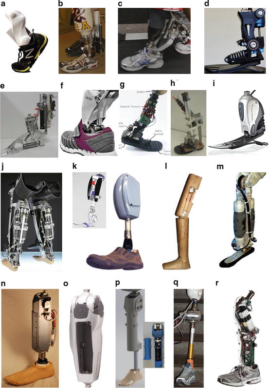
Twenty-five years later still only a few commercialized systems provide the possibility to inject energy and to create joint torques actively. Twenty-six systems including prototypes and commercialized systems are listed in Tables 5.3 and 5.4 (Appendix). Some of them have a couple of previous design generations. Non of the systems is addressing an active hip joint. So far only powered systems for ankle (Fig. 5.8a–j, r) and knee (Fig. 5.8k–r) are described in literature.
The first commercialized active foot is the Proprio Foot (Ossur, Fig. 5.8i). It has the possibility to lift the toe during swing phase to adapt to terrain and to prevent from trips or falling. Different sensors (accelerometer, angle sensor) detect the actual state (walking flat, stairs, slopes, sitting, standing) and set a linear actuator to the appropriate position corresponding to a defined ankle angle. For this motion events like take off or touch down are identified. To get a better pattern recognition also the last step is taken into account. A similar actuation concept was used for the prosthetic ankle concept introduced in [155].
A further commercialized concept for an active foot is from iWalk (Fig. 5.8f). They introduced the BiOM Power Foot, an active prosthesis to replace the ankle joint [83]. Achilles tendon like elastic function (spring) is combined with a motor that mimics calf muscle behavior. By this method not only swing phase adaptations like in the Proprio Foot but also active powered push off becomes possible.
Active motor support for the knee joint is provided in the Power Knee (Ossur, Fig. 5.8o). The first generation of the knee joint was launched in 2006. The second much more compact version is available since 2011. Knee extension while ascending stairs and slopes or also while standing up from sitting is supported by a motor. During sitting down or descending stairs and slopes the motor can dissipate energy. During take off the motor rises the heel actively for swing flexion. In addition it assists at stairs or slopes for positioning the knee adequately for touch down. Like in the BiOM Foot a spring is assisting the motor to some extend by storing energy in a specific phase (yielding, stance phase flexion) and releasing it later. The same approach is used in [102]. A powered knee joint prototype with an antagonistic SEA design (Fig. 5.8n) could increase amputee’s average self-selected walking speed by 17 % from 1.12 to 1.31 m/s compared to a C-Leg. At fixed speed (1.3 m/s) metabolic costs decreased by 6.8 % using the powered prototype in comparison to the semi-active knee joint.
Various powered prototypes (Tables 5.3 and 5.4) are in commercial or university development. Concepts are including single ankle and knee prosthetics but also approaches combining both joints actuated in one design. At the Vanderbilt University (Nashville) a combination of powered knee and ankle was developed [151], (Fig. 5.8r). The concept will be further developed and commercialized by Freedom Innovations [45].
A concept using electrical motors to do cheap design knee prosthetics is introduced in [82, 90], (Fig. 5.8l). The motor should not replicate torque profiles of walking or stair climbing but it should enable the person to flex or extend the knee in low load or no load conditions.
Powered ankle joints for walking (Odyssey Ankle, Fig. 5.8a) and running (Fig. 5.8c, d) were developed at Springactive [149] and Westpoint Military Academy [71] based on previous designs (Sparky, Fig. 5.8b) from the Arizona State University [8].
Walking should also be achieved with the PANTOE 1 (Fig. 5.8g) foot prosthesis developed at the Peking University [182, 186]. In addition to the common concepts an activated toe joint is integrated in the design.
A mixture of prosthetic and orthotic design is developed at the TU Darmstadt. The Powered Ankle Knee Orthoprosthesis (PAKO, Fig. 5.8j) should be used to evaluate elastic actuator design and control concepts for humanoid locomotion. Therefore a mechanism to change stiffness of a spring in the SEA is included in the design.
5.5.1 Mechanics
5.5.1.1 Actuator Concepts
All commercial available active prosthetics and the most of the prototypes using electrical motor technology for driving the ankle or the knee joint. In addition some of them include different kinds of elastic concepts. Series, parallel or unidirectional parallel alignments of motor and elastic element are used aiming at a reduction of motor requirements. Peak power (PP), which corresponds to motor size and energy requirements (ER), which defines battery size and operation time are characteristics to be decreased in comparison to direct drive (DD) systems.
Most of the active prosthetic prototypes try to mimic torque ankle profiles of the ankle and knee joint. Some of them are only acting with minimal power efforts [44, 155] to change for example ankle angle for ground clearance in flight phase or to adapt ankle angle to slopes.
In order to get a higher power density than in electrical motors also hydraulic or pneumatic actuators could be used. In [122] a design is introduced that provides energy injection for the ankle and the knee joint by linear hydraulic actuators driven by a single pump. So push off can be supported at the ankle, early swing at the knee and the ankle joint. During stair climbing and late swing the knee can be powered. A special feature of the prosthesis is to work in active mode or also as a semi-active device like the C-Leg.
Pneumatic actuation was demonstrated with the pleated pneumatic artificial muscles (PPAM) concept [170]. The system was able to produce required torques for an artificial ankle joint in walking. PPAM pressure was generated by a stationary compressor in the laboratory.
Using PPAM, a stiffness adaptation for different speeds was possible. Required stiffness was estimated by a linear regression on human ankle torque-angle curves.
Pneumatic actuation can also be found in a knee prosthesis [175], (Fig. 5.8m). To become independent of external pneumatic supply this group investigates liquid propellants as energy source. The monopropellant, a reaction product of a catalytically decomposed liquid, should be able to provide large power output and long operation times. For a mobile solution the compact energy storage of the propellant will be beneficial [146].
5.5.1.2 Spring Configurations
For the different leg joints and also different tasks optimal elastic actuator configurations can be identified. The challenge is to identify a most multifunctional solution that can provide benefits in various daily life activities. In terms of energy consumption the primary focus should be on the most common daily life activities like walking or just standing in place. But also energy and power requirements in stair climbing, standing up, sitting down, walking slopes or running could be included in the choice for an elastic actuation concept.
Inspired by muscle modeling different actuator solutions can be considered. Solutions with series elastic elements (SE) were used in [121]. Parallel elements (PE) to the contractile element (CE) were omitted in this study because many authors reported only negligible passive parallel forces. In contrast the Hill Model includes a SE and a PE. Different solutions exist with the CE and the SE together in parallel to the PE [183], (Fig. 5.9e) or only the CE in parallel to the PE [111], (Fig. 5.9c). In addition to the conventional elastic concepts unidirectional springs, coming into action at a defined condition (kinematic, kinetic), can be considered.
Such an approach is used in [151] where the spring comes into action at an ankle angle of about 5∘ of plantarflexion. The BiOM ankle prosthesis [37] includes an SEA in addition, to extend the system to a scheme similar to Fig. 5.9i. In an earlier version of the device the unidirectional spring is mentioned to be engaged at 0∘ [6]. A spring in series (Fig. 5.9b) with a much smaller stiffness than in the BiOM ankle is included in the Robotic Tendon approach of Sparky. Stiffness is defined using power optimization calculations [76]. Especially the long lever arm between ankle joint and actuator causes this design difference [59]. In contrast, in the BiOM ankle series stiffness is chosen based on open-loop force bandwidth [6]. An extended version of the Robotic Tendon approach is introduced in [71, 140]. For running two parallel elastic actuators were included in the design to achieve the required power demands.
Fig. 5.9
Various concepts for elastic actuators combining a motor (M) with series (SE), parallel (PE) and/or unidirectional parallel (UPS) springs. In addition it could be possible to include clutches (C) or damping elements (j and k)
A series spring approach is also used for the AMP foot 2.0 [18], (Fig. 5.8e). In contrast to the approaches using motors with over 150 W the design requires only a 60 W motor. This solution is possible by combining two basic mechanisms. A series spring, which is decoupled from ankle motion, is loaded with a constant power by the small motor during the entire stance phase. A second spring is saving energy in a similar way like the forefoot part in ESAR feet. During push off the passive spring returns its energy. In addition a clutch is used to release the energy from the motor-spring combination (Fig. 5.9f). On the one hand this approach provides the advantage of less peak power requirements for the motor. This could potentially save space and weight if the required clutch mechanism is small enough. In contrast to the mechanisms used in [37] and [72] the energy return cannot be modulated in the same way. It is like a catapult that just releases the energy if the trigger is pulled. The interaction with the amputee must be programmed carefully to match desired patterns. To which extend this approach can handle different daily life situations like different speeds, slopes and stairs should be further investigated.
Two SEA’s are used in the PANTOE 1 [182, 186]. The ankle prosthesis includes one SEA for ankle plantar and dorsiflexion. Another SEA modulates toe joint motion. It is envisioned that the active prosthetic toe joint can improve several biomechanical parameters for the foot like RoM, angle velocity and energy output. Higher walking speeds should be achieved in comparison to rigid foot design.
Systematic analysis on elastic actuator concepts that reduce energy requirements (ER) or peak power (PP) were published for the ankle [39, 59, 60, 173], the knee [58, 173] and the hip [173] joint. Methods for calculations base on [76]. In order to decrease power, actuator velocity or actuator force could be reduced. A series spring has the capability to decrease motor velocity. A parallel spring has the capability to reduce motor force.
Especially for the ankle joint high benefits could be identified for the motor when using a series spring with optimal stiffness in comparison to a direct drive. In terms of ER the mean advantage for five different speeds between 0.5 and 2.6 m/s was about 64.7 % for running and 25.8 % in walking using an SEA. A PEA (Fig. 5.9c) could reduce ER to less extent. 45 and 12.2 % were possible respectively. A combination of both elastic structures (SE+PEA, Fig. 5.9d) results in an energetic advantage of 52.8 % in running and 17.9 % in walking for the elastic actuator.
In terms of peak power highest reductions were identified for the SE+PEA system (81.8 %) in running. The force reduction by the parallel spring contributes most to reduce power requirements. A single PEA had already a mean advantage for the five speeds of 79 %. An SEA could reduce PP by 68.5 % in running.
For walking a similar trend was identified. An SE+PEA had highest benefits (70.4 %). Lower advantages were identified for the PEA (62.5 %) and the SEA (48.3 %).
Unidirectional parallel springs at the ankle joint (Fig. 5.9g–i) can have similar power advantages like the PEA. In addition it is possible for some speeds to get lower ER than in PEA [39].
At the knee joint energetic benefits of 5–29 % could be achieved by an SEA in comparison to a DD in walking (0.5–2.6 m/s). No or only little PP (high speeds up to 31 %) reductions were possible in walking, when considering that negative work has to be done by the motor (no passive damper or energy harvester to perform negative work). For running (0.5–4 m/s) energetic reductions of 40–71 % and PP reductions of 54–78 % were identified.
For the hip joint calculations on possible reductions were done for walking at 0.8 and 1.2 m/s. A PEA could reduce torque by 66 % for flexion and extension. A reduction of 53 % was identified at the hip for abduction and adduction [173]. Using an SEA 60 % reductions of torque could be identified for the same motion.
5.5.1.3 Damping
Next to springs also dampers can help to reduce actuator requirements in powered lower limb prosthetics. Negative joint power (Fig. 5.6) can be introduced by these passive prosthetic parts. Due to microprocessor controlled mechanisms damping ratio can be changed by semi-active prosthetic knee joints to adapt to variations in walking speed. Eccentric muscle function can be replaced. A similar function can be realized by a motor using energy for decelerating the motion. In contrast also energy harvesting could be possible for the same process. An energy harvester integrated in a single knee brace [32] could generate about 2.4 W while generative braking in the late swing phase. In [58] it was shown that using an SEA setup at the knee joint needs nearly no positive work in walking and running. Thus it could be possible to generate electricity at the prosthetic knee joint to use it for powering the artificial ankle joint. A similar idea to use damping work, store it and release it later to support push of is realized in a prosthetic foot prototype [21]. Damping work from impact during touch down is used. A similar damping function is realized in biology by the heel pad [48]. Additionally to the heel pad also wobbling masses are damping impacts in locomotion [118]. Similar systems are not included in current prosthetic designs. Partially shock absorbing elements are used to replace this function.
For a prosthetic ankle joint similar to the eccentric phases of the knee joint it is possible to reduce energy requirements for a motor when using a damper. Possible operation phases are when replacing tibialis anterior function after touch down. Also while descending stairs negative work could be realized by a damper to mimic eccentric plantar flexor work. Eslamy et al. [40] predicted benefits of up to 50 % for PP and about 26 % for energy requirements using an SEA combined with a damper in comparison to a pure SEA (Fig. 5.9k). Similar concepts combining motors, springs and dampers for a powered ankle joint can be found in a patent from 2012 [67]. In level walking no benefits of a continuous acting damper could be identified for the evaluated systems [40]. Controllable dampers that are active only for some gait phases might change the results.
Related posts:
 Effective Neural Representations for Brain-Mediated Human-Robot Interactions
 Robotic Systems for Gait Rehabilitation
 A Human Augmentation Approach to Gait Restoration
Stay updated, free articles. Join our Telegram channel

Full access? Get Clinical Tree


