Fig. 40.1
(a, b) Posterior cervical anatomy
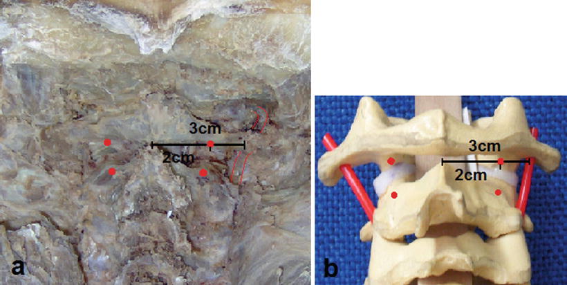
Fig. 40.2
(a, b) The vertebral artery is found 3 cm away from the midline on the lateral trajectory to the C1 posterior arc
Additionally, C1 lateral-mass and C2 pedicles were measured, concluding that at least 3.5–4.0 mm diameter screws can be inserted, although this could vary from patient to patient making necessary an exhaustive preoperative evaluation and planning, and fluoroscopic confirmation during surgery [9, 10, 20].
Surgical Technique
To preserve the occipito-cervical tension band, decreasing morbidity of traditional procedures and less postoperative pain, we performed a prospective non-randomized study starting in May 2007 [2] using a minimally invasive trans-muscular approach through a 2.5 cm bilateral paramedian skin incision (Fig. 40.3a), using the access MIS platform Maxcess® (Nuvasive Inc., San Diego, CA, USA) (Fig. 40.3b) and subsequent placing screws according to the modified Harms technique (Fig. 40.3c).
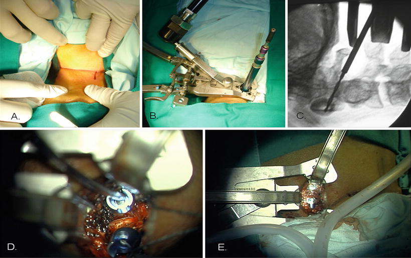
Fig. 40.3
(a–e) The paramedian approach with tubular retractor for screw insertion into C1 and C2
This approach uses a progressive tubular dilators system through the superficial nucal musculature (trapezius and semispinalis capitis) and then through the anatomical corridor previously described between the posterior major rectus capitis and the inferior obliquus capitis. A three valve spreader Maxcess® with optical fiber light is then placed, allowing good exposure and illumination of the working area (Fig. 40.3b). Under fluoroscopic guidance, the system is anchored on the access point of C2 pedicle, trying to avoid obstructing the posterior arch of C1 during opening of the retractor. With monopolar cautery bony surface of C2 is exposed, following it until the lateral border C1–C2 articulation is also visualized. At this point an epidural venous plexus usually bleeds, but it’s effectively controlled with a combination of bipolar cautery and Spongostan®. C1–C2 bone joint surface is exposed and the C2 root identified, and then coagulated and sacrificed to allow adequate insertion of the screw. At this point 3.5 mm diameter polyaxial screws are inserted using Harm’s technique (Fig. 40.3c, d). The articular surfaces of C1 and C2 are decorticated using micro-curettes and demineralized bone matrix (Grafton® DBM-Putty, Osteotech®, Inc., New Jersey, USA) mixed with bone marrow aspirated (BMA) is placed inside the joint to obtain second fusion (Fig. 40.3d, e). The same procedure is made in the contralateral side in the same way.
Clinical Experience
Until December 2012 a total of 21 patients was treated using this technique; mean age was 57.5 years old. Nine patients presented unstable C2 fracture and 12 patients atlanto-axial instability secondary to RA. Mean surgical time and blood loss was 193.7 min and 403.5 cc, respectively. Patients experienced minimal postoperative pain and were discharged 46.8 h after surgery. Additionally, no hardware failures were present.
Clinical Examples
Case 1
Forty-seven-year-old male patient, consulting with posterior neck pain, occipital headache, and weakness on left side body, 3 days previously patient fallen with cervical trauma in flexion.
Neurological exam showed pain on C2 dermatome bilaterally, 4/5 left hemiparesia without Babinski sign and left patchy distribution hemi-hypoesthesia for superficial tact.
Cervical X-ray films showed dens fracture type II with instability (Fig. 40.4a, b).
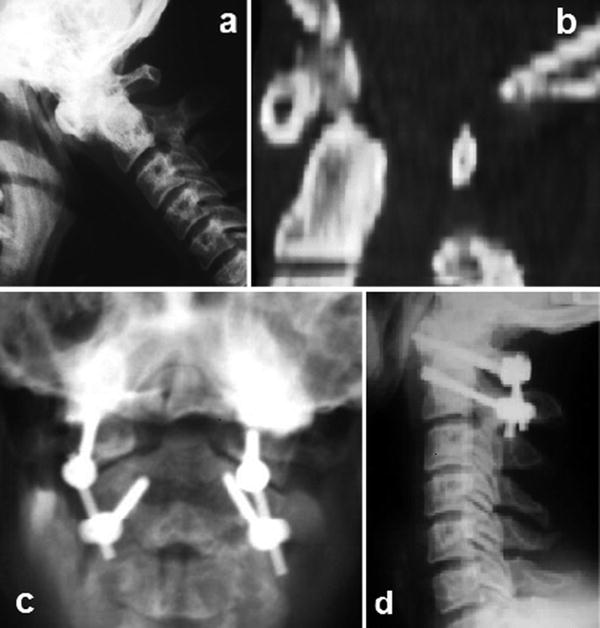
Fig. 40.4
(a, b) Case 1 preoperative and postoperative X-rays
We performed a minimally invasive C1–C2 fusion procedure using polyaxial 3.5 mm diameter screws on both sides. No intraoperative complications occurred and blood loss was approximately 300 mL. Hospital stay was 43 h, the patient showed motor recovery in the early postoperative period (Fig. 40.4c, d). After 1 year of follow-up patient has neither pain nor weakness and instrumentation looks in good position.
Case 2
Seventy-year-old female patient with 30 years history of rheumatoid arthritis, she had noticed sensation of cervical instability and “cracking” during cervical motion, associated posterior neck pain irradiated to upper dorsal region, numbness and weakness of the upper limbs.
On exam patient had bilateral hyperreflexia, as well as Hoffman’s sign bilaterally without motor deficit. Magnetic resonance image (MRI) scans showed pannus odontoideum with posterior dens luxation and compression over the spinal cord without T2 signal of myelopathy. Dynamic X-rays films revealed that the atlanto-odontoid interval reached more than 5 mm in length (Fig. 40.5a).
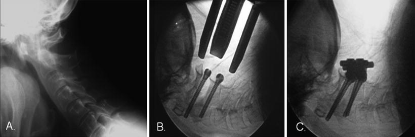


Fig. 40.5
(a–c) Case 2 preoperative, intraoperative, and postoperative X-rays
Related posts:


Stay updated, free articles. Join our Telegram channel
Full access? Get Clinical Tree
