Fig. 1
(a) Cumulative number of publications with mouse SAH models, listed by year of publication. (b) Diagram showing the shares of the models in %
Material and Methods
Animals
Experiences and observations presented are based on experiments performed using ddY (10–12 weeks, 21–26 g, Kyudo Co Ltd., Japan) as well as C57BL/6N (10–12 weeks, 21–26 g, Kyudo Co Ltd., Japan) mice.
Perioperative Management
Standard microsurgical instruments including a bipolar forceps were used. The operating microscope had a 7- to 45-fold magnification (Arms Systems Co. Ltd., Japan). Mice were anesthetized with isoflurane (Escain, Mylan Co. Ltd., Japan): 5 % induction, 1.5 % maintenance, using a facemask. A thermostatically regulated, feedback-controlled heating pad (NS-TC10, Neuroscience Inc., Japan) was used to maintain body temperature at 37.5 °C. Intracranial pressure was measured using a fiber-optic micro pressure transducer (Samba Sensors AB, Goteborg, Sweden). In prone position, the tip of the sensor was placed on the left scull base.
Surgical Procedure
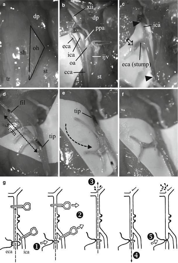
The mice were placed in a supine position. A midline incision was made in the neck. The underlying subcutaneous tissue was separated in a blunt fashion and the submaxillary glands were gently pushed aside. A triangle formed by the sternohyoid/omohyoid, sternocleidomastoid, and posterior belly of the digastric muscle was visualized (Fig. 2a). By dissecting the triangle, the neurovascular bundle consisting of the common carotid artery (CCA), vagal nerve, and internal jugular vein was visualized in the depth (Fig. 2b). The CCA was isolated, marked, and gently lifted with a holding thread. The CCA was traced cranially until the bifurcation. At the bifurcation, the occipital artery (OA)—the first branch of the external carotid artery (ECA)—could be seen beside the internal carotid artery (ICA). The ECA was traced in a cranial direction after the digastric muscle was pushed laterally (Fig. 2b). The ECA was traced until its further branching, preserving the ECA segment as long as possible. After a ligation, the ECA was coagulated and cut. Then, the OA was sacrificed. Afterwards, the ICA, which runs in an inferior-medial direction (point of view), was traced. The removal of the carotid body might be necessary because it might hamper the view. Next, the pterygopalatine artery (PPA) arising from the extracranial section of the ICA was identified (Fig. 2b). The tiny branches from the glossopharyngeal nerve lying on the ICA/PPA bifurcation were gently pushed cranially to gain an adequate view. Once the paths of the ICA and PPA were visible, the PPA was sacrificed (Fig. 2c). If the PPA was not sacrificed, the filament tended to take a via falsa toward the PPA instead of the ICA. A ligation was prepared on the most proximal part of the ECA stump. Mini clips (Roboz Surgical Instrument Co., Inc., USA) were placed at the ICA and CCA. An arteriotomy was performed on the distal part of the ECA stump (Fig. 2c). A 5-0 nylon filament (0.1-mm diameter, Ethilon, Ethicon Inc., USA) was pushed through the arteriotomy toward the ICA (Fig. 2d) until the tip reached the occluded part by the distal clip. One might consider rotating the ECA stump in the inferior direction before inserting the filament, so that the path for the filament would be straight. However, the tip of the filament can get stuck at the bifurcation while it is being advanced. Therefore, we inserted the filament at a more “physiological” angle ≤90° (Fig. 2d). Once the tip overcame the bifurcation, the stump with the filament was rotated inferiorly (Fig. 2e). The clips were removed and the filament was pushed further cranially. After removal of the clips, retrograde bleeding might occur. Gentle tightening of the prepared ligation avoids this. This inconvenience might be further avoided if the proximal clip was left in place and removed at the end of the procedure, i.e., after the perforation and complete withdrawal of the filament and ligation. However, accumulated experience revealed that the latter maneuver decreases the degree of success and volume of SAH, possibly because of rapid activation of the coagulation cascade. Therefore, we recommend the procedure as shown in Fig. 2g. The filament was gently pushed forward (~5 mm) until some resistance was felt. The filament was pushed an additional ~1 mm further to perforate the vessel. The filament was withdrawn quickly and the prepared ligature tightened (Fig. 2f). After ensuring hemostasis, the wound was adapted and sutured.


Fig. 2
Step-by-step illustration of the cWp model. (a) The triangle formed by the sternohyoid (sh)/omohyoid (oh), sternocleidomastoid (st), and posterior belly of the digastric muscle (dp) is shown. tr trachea. (b) the neurovascular bundle including the common carotid artery (cca) and internal jugular vein (ijv) is visualized. eca external carotid artery, ica internal carotid artery, oa occipital artery, ppa pterygopalatine artery, xii hypoglossal nerve. (c) A stump of the eca is created. The oa and ppa are sacrificed. The Arrowheads indicate the point where the clips are placed. The arrow indicateds the location of the arteriotomy. (d) The filament (fil) is pushed through the arteriotomy toward the ica. Note the phsiological angle between eca and ica/cca. tip tip of the filament. (e) The stump with the filament is rotated inferiorly once the tip overcome the bifurcation. (f) After perforation, the filament is withdrawn quickly and the prepared ligature tightened
Evaluation of SAH and Histological Examinations
To evaluate the degree of hemorrhage, animals were killed at day 0, 1, and 2 after SAH. The brains were quickly removed and photographed under the operating microscope. For histological examination, euthanasia was performed by transcardial perfusion–fixation at day 2 after SAH. The brains were removed, postfixed and paraffin embedded. The blocks were sliced into 7-μm sections using a microtome (Leitz 1512 Microtome, Wetzlar Germany). Hematoxylin and eosin (HE) staining was performed for overview and CVS identification. For the assessment of neuronal injury, Fluoro-Jade C (FJC) staining (Merck Millipore, USA) was performed as previously described [21]. To evaluate the occurrence of apoptotic neurons, terminal deoxynucleotidyl transferase dUTP nick labeling (TUNEL) staining was performed (Roche Diagnostics, Germany). The numbers of FJC- and TUNEL-positive cells were determined in randomly selected regions of interest in the hippocampal region and cerebral cortex. Because microthrombosis has been discussed more recently as an additional explanation for neuronal injury after SAH, we investigated the occurrence of microthrombosis by immunohistochemistry (sheep anti-fibrinogen antibody; LifeSpan, BioSciences, USA).
Results
General Observations
The perforation caused a sharp increase in ICP. After withdrawal of the filament, the full reperfusion through the ICA caused a further increase in ICP, reflecting a full-scale SAH. We could clearly observe brief decreases in the respiration and pulse frequency in this phase, presumably reflecting a Cushing reflex, as in previous reports [4, 8]. The distance until vessel perforation was achieved varied by 1–3 mm among the cases. In our experience, this distance cannot be standardized by any means. The distance might vary 1~2 mm depending on the site of the arteriotomy, or on several other factors, such as the positioning of the animal’s head. Therefore, ICP monitoring is probably the method of choice to confirm a successful induction of SAH [4]. However, with accumulating experience, one might successfully perform it without the need for monitoring, because animals clearly showed a Cushing reflex.
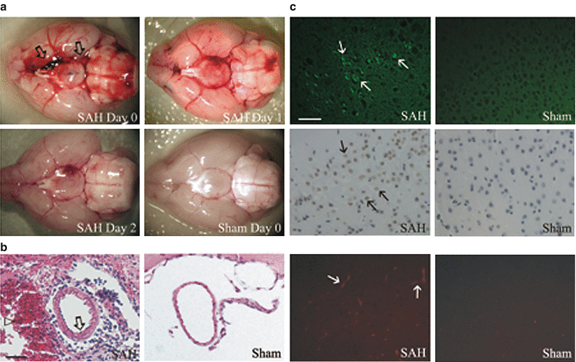
The presence of subarachnoid blood could be verified at all examined time points. The volume of subarachnoid blood varied among the cases. The amount of blood decreased gradually over time (Fig. 3a). Closer inspection of the ventral surface of the brains revealed that the filament perforated the circle of Willis in the vicinity of the ICA/posterior communicating artery (PcomA) bifurcation. In the literature, the majority of reports claimed to have caused a perforation in the vicinity of the anterior cerebral artery (ACA) [2, 5, 6, 8, 10–14, 17, 20, 22–24]. Taking the anatomical considerations and the stiffness of the filament into account, the ability to achieve a perforation at the ACA might be considered somewhat doubtful. However, because successful SAH could be induced, the exact location of the perforation might be irrelevant.


Fig. 3


(a) Representative brain specimens. Subarachnoid blood in the basal cisterns is clearly visible at day 0 (arrows). The amount of blood decreased with time. No SAH was seen in sham animals. (b) Representative image sections of the distal ICA showing morphological signs of CVS with thickened vessel wall in SAH (arrow). Note the subarachnoid blood (arrowhead). Bar: 50 μm. (c) Upper row: FJC-positive neurons after SAH (arrows). Middle row: TUNEL-positive cells after SAH (arrows). Bottom row: Fibrinogen-positive microthrombi after SAH (arrows). Bar: 100 μm
Stay updated, free articles. Join our Telegram channel

Full access? Get Clinical Tree


