Fig. 4.1
A representative subject’s ankle rotations in DP, IE, and ML directions during the straight walk and step turn
Table 4.1 shows the average ROM of the subjects during the straight step and step turn stance periods. The maximum and minimum angles and maximum angular velocities observed for the representative subject in Fig. 4.1 can also be seen in Table 4.1. Table 4.2 shows the average rotations and the difference in angles from the turning step to the straight step in each phase. The range of motion of each subject’s ankle about the three axes of the ankle and their average rotations during the stance periods were calculated and used to find the averaged percent change from straight walk to step turn with respect to their ROM during the straight step (Table 4.2).
Table 4.1
ROM of ankle during the stance in straight walk and step turn
ROM of straight step stance period (deg) | ROM of step turn stance period (deg) | |||||||
|---|---|---|---|---|---|---|---|---|
Degrees | Standard error | Degrees | Standard error | % Change | Maximum anglea | Minimum anglea | Maximum angular velocitya | |
DP | 33.9 | 0.65 | 31.6 | 0.62 | −7.4 | 13.03° | −21.58° | 120°/s |
IE | 15.69 | 0.52 | 20.6 | 1.06 | 23.8 | 19.72° | −4.248° | 101°/s |
ML | 22.09 | 0.6 | 16.8 | 0.65 | −31.9 | 7.69° | −13.75° | 144°/s |
Table 4.2
Average angles at different phases of stance in straight step and step turn
Straight step average (deg) | Standard error | Turning step average (deg) | Standard error | Angular change (deg)a | % Changeb | |
|---|---|---|---|---|---|---|
DP heel Strike | −8.72 | 0.80 | −9.68 | 0.95 | −0.95 | −3.0 |
DP flat foot | 2.34 | 0.63 | 0.36 | 0.64 | −1.98 | −6.5 |
DP toe off | 10.59 | 1.24 | 1.37 | 0.90 | −9.22 | −29.2 |
IE heel strike | −1.72 | 0.53 | 5.90 | 0.63 | 7.61 | 46.6 |
IE flat foot | −2.93 | 0.27 | 6.51 | 0.22 | 9.44 | 60.5 |
IE toe off | 1.44 | 0.45 | 13.61 | 0.46 | 12.17 | 82.0 |
ML heel strike | −5.34 | 0.57 | 0.34 | 0.62 | 5.68 | 25.6 |
ML flat foot | −0.90 | 0.45 | −3.55 | 0.41 | −2.65 | −12.8 |
ML toe off | 5.53 | 0.32 | −6.53 | 0.65 | −12.06 | −58.0 |
The duration of the combined phases of heel strike and loading response, mid stance, and terminal stance and pre-swing phases were determined and used to measure the average angles at each combined phase.
There was a modest decrease of ROM in DP direction during the step turn compared to the straight step. ROM in the IE direction increased by 23.8 % indicating the significance of the IE role during turning. A significantly smaller range of motion in ML may suggest a higher stiffness in that axis of rotation necessary to transfer the reaction forces from the ground to the body.
As the step progressed through the gait cycle, noticeable differences were observed between the straight step and step turn for all subjects. DP displacement started at a similar initial angle as the straight step at the heel strike (−9.68° of dorsiflexion) but progressively showed less plantarflexion at toe-off (1.37° in step turn compared to 10.37° in straight walk). IE displacement started with 5.9° of inversion at heel strike and increased to 13.6° at toe-off during the step turn suggesting a gradual increase in inversion to lean the body toward the inside of the turn. At the heel strike of the step turn, ML displacement had an increase of 5.68° of medial rotation compared to straight walk that may suggest an anticipatory motion of the foot. The difference in lateral rotation during straight step and step turn at the toe-off increased to 12.06°.
4.3 Multi-axis Ankle-Foot Prototype
The result from the ankle rotations in three DOF suggested that a multi-axis mechanism in a prosthesis may enhance gait efficiency by adding control of ankle inversion/eversion during turning. This novel design is anticipated to enable the device to adapt to uneven and inclined ground surface condition and allow the amputees to benefit more from their prosthesis rather than using their hip joint; enabling a more natural gait with less stress in other joints.
Based on this concept, a prototype cable-driven ankle-foot prosthesis with two controllable degrees of freedom (Fig. 4.2) was designed to evaluate the feasibility of controlling a 2 DOF ankle joint. The design goals were to meet the ROM and angular velocity required for straight walk and step turn while providing sufficient torque for propulsion.
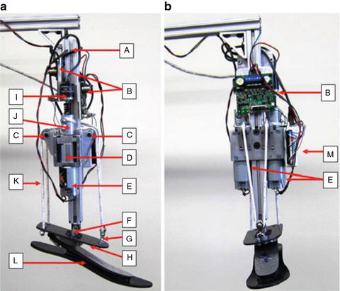

Fig. 4.2
Prototype of a multi-axis powered ankle-foot prosthesis (a) in plantarflexion and (b) in inversion
The device consisted of a pylon (A), two DC motors (E) and planetary gearheads (D) that are powered by two motor controllers (B) that receive signals from a DAQ board (M) connected to a remote computer and two quadrature encoders (I). Two cable drums (J) transfer the required torque to the ankle through a nylon rope (K) that passes through two pulleys (C). The rope is looped around both the cable drums and secured to prevent slippage (Fig. 4.3 ). A universal joint (F) connects the pylon to the foot and an elastic carbon-fiber plate. The rope is attached to a carbon fiber plate (H) that is connected to a commercially available prosthetic foot (Otto Bock Axtion®) (L). In the aft side of the carbon fiber plate, the rope is mounted at both sides of the longitudinal axes of the foot. At the fore side, the rope passes through a pulley (G) that is connected to the carbon fiber plate by a universal joint. The mechanism is capable of both dorsiflexion-plantarflexion when the motors rotate in opposite directions and inversion-eversion when the motors rotate in the same direction. Also, any combination of DP and IE can be achieved by combining different amounts of rotations at each motor.
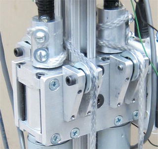

Fig. 4.3
Cable drum connection to avoid cable slippage
The proposed design with two controllable DOFs relies on the fact that three points are sufficient to define a plane in the space. As shown in Fig. 4.4, the three points (A, B, C) can be used to define rotations of the foot relative to the pylon about the X and Y axes that are equivalent to DP and IE, respectively. If the motors apply forces in the same directions, for example in the negative Y direction, points A and B will move downwards, while point C moves upwards, resulting in dorsiflexion. If the motors move in opposite directions, for example the right motor pull the rope in the positive Y direction and the left motor pulls the rope in negative Y direction, point A moves upwards, while point B moves downwards generating foot eversion. At point C, a pulley is mounted to the plate using a universal joint. Because point C is located on the axis of symmetry of the plate and the rope passes through the pulley at point C, no DP motion is generated. The carbon fiber plate is a fundamental component of the design. The carbon fiber plate acts as a spring element in series with the cable and the foot. The cable needs to be always in tension to assure proper control over the foot and keep the carbon fiber plate under a bending moment. This assures the cable has a sufficient tension over the ROM of the foot providing that it can be controlled to mimic the mechanical impedance of a human ankle.
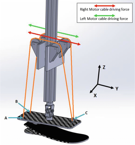

Fig. 4.4
A simplified drawing of the cable driven mechanism showing three interaction points A, B, and C between the cable, carbon fiber plate, and motor drive forces
Providing sufficient power and torque at the ankle joint without significant increase in the weight of the powered prostheses is a challenging issue. For example, Hitt et al. used two parallel actuators to increase the power output for walking in increased speed [33]. The steering mechanism proposed here also use two actuators; however, the design allows for generating a torque component in lateral plane. The cable driven design, besides the ability to control the ankle in two DOF, may provide a significant flexibility in managing the inertia of the ankle-foot prostheses too. A detailed description of the components used in this proof of concept prototype can be found in [89].
4.4 Evaluation of the Design Concept
The developed prototype has been evaluated for meeting two criteria. First, the design kinematics should be capable of regenerating the same ankle rotation as the human ankle during the stance and swing phases of gait. Second, the multivariable impedance of the prototype ankle needs to be comparable to the mechanical impedance of human ankle.
4.4.1 Kinematic Evaluation
Presently, two optical quadrature encoders (200 pulses per revolution) provide position feedback to a remote computer that uses a proportional plus rate controller to control the relative position of the foot with respect to the pylon. The controller uses a look-up table with recorded angles of the representative subject of the motion analysis experiment in both DP and IE. The input and output angles to the controller can be seen in Fig. 4.5 where the robot is moving at 50 % of the walking speed. For ease of comparison, the output plots have a time shift to remove the 80 milliseconds delay of the output. Also, all signals are filtered with a low-pass filter with a cutoff frequency of 5 Hz to remove sensor noise from the output signal. The current prototype was developed as a proof of concept to validate the design kinematics; therefore, faster motors and sensors with lower noise levels will be used in future designs.
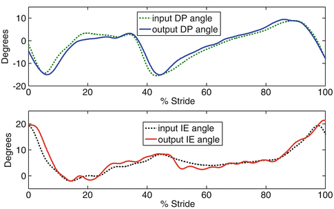

Fig. 4.5
Input and compensated output for time delay (80 ms) of the ankle-foot prosthesis during swing and stance periods of a step turn at 50 % of the walking speed with no load
4.4.2 Mechanical Impedance Estimation
Recently, hierarchical control strategies have been developed for impedance control of active prostheses [39, 30]. The higher level control identifies the gait cycle, and the lower level control regulates the actuators for a proper impedance characteristics. Following the same strategies, an ankle-foot prosthesis can be designed to have an initial mechanical impedance similar to a human’s ankle. This may provide a faster modulation of the ankle impedance based on the state of the gait cycle.
The purpose of this evaluation was to identify the passive impedance of the prosthetic device and compare it to the impedance of human subjects. The impedance estimation experiment setup was similar to the procedure reported in [79, 78], where an Anklebot® was used to apply random torque perturbations to the ankle joint in DP and IE directions with a bandwidth of 100 Hz and record the provoked ankle angles. A stochastic system identification method was used to estimate the multivariable mechanical impedance of the ankle using the collected data. Similar procedures were used for estimation of passive mechanical impedance of the ankle-foot prosthesis while all its controllers were turned off. The experimental setup can be seen in Fig. 4.6, where the two devices were attached mechanically to each other. The Otto Bock Axtion® foot and its rubber foot shell were inserted in the same type of shoe used in human tests to ensure consistency in the experiments. Similarly, the same test was done on a representative human subject for comparison with the prosthesis. Impedance test of the human subject was performed with both relaxed muscles and 10 % MVC of the tibialis anterior following the procedures described in [79]. The EMG signals were monitored using a Delsys Trigno Wireless EMG System® with surface electrodes placed at the belly of the tibialis anterior. The EMG signal was sampled at 2 kHz and the root-mean-square value of a window of 13.5 ms of data calculated and displayed on a computer screen in order to provide a visual feedback to the participant for maintaining constant muscle activity. The results can be seen in Figs. 4.7 and 4.8.
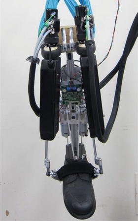
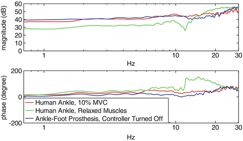
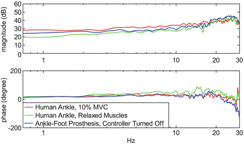

Fig. 4.6
Anklebot attached to the prosthetic foot to measure the mechanical impedance of the ankle-foot prosthesis

Fig. 4.7
Plots of the magnitude and phase of the impedance in DP rotation of the prosthetic robot and a human subject with relaxed muscles and 10 % cocontraction

Fig. 4.8
Plots of the magnitude and phase of the impedance in IE rotation of the prosthetic robot and a human sample with relaxed muscles and 10 % cocontraction
Figure 4.7 shows the Bode plots of the mechanical impedances in DP direction for prototype prosthesis, human subject’s ankle with relaxed muscles, and human subject’s ankle with 10 % MVC. The quasi-static stiffness of the prototype prosthesis, which is the impedance magnitude at low frequencies, was 39.5 dB (94 N.m/deg) in DP at 1 HZ. Also, it shows a relatively linear impedance and phase over the frequency range of interest (0–5 HZ). The human subject showed similar stiffness in DP for the co-contraction testes and lower stiffness in passive test when compared to the prosthesis. IE impedance magnitude (Fig. 4.8) of the prosthesis was between the active and passive stiffness of the human sample with a value of 24.24 dB (16 N.m/deg) at 1 Hz.
Stay updated, free articles. Join our Telegram channel

Full access? Get Clinical Tree


