Fig. 10.1
Traumatic subluxation of the dens in a 3 years old girl. (a) CT Scan reconstruction. (b) Reduction in halo. (c) Halo reduction. (d) Flexo-extension x-ray after halo removal
In all other cases surgical treatment should represent the first choice.
Biomechanical Analysis of Surgical Treatments
The goal of the surgical treatment is to provide a stabilization of the unstable segment (i.e. the axial part of the cervical spine) as strong as possible. On the other hand, as every posterior stabilization leads to loss of motion, the ideal treatment should be the most strong and the least invalidating.
Many biomechanical studies have investigated the ability of the different treatments of stabilizing the C1-C2 segments. According Sim et al. [34], who measured the range of movement and the neutral zone of cadaver specimens after different techniques of stabilization, posterior wiring (PW), transarticular screws (TA) and screws in C1 lateral masses combined with C2 screwing (C1LM-C2 PS) are all able to stabilize an unstable axis in flexion–extension. However, posterior wiring couldn’t give enough stability at rotational and lateral bending tests, and were therefore considered insufficient. The three-point reconstruction, using TA and PW provided the best results in all the tests, but also the C1LM-C2PS achieved a sufficient stability in the three planes.
The most recent review has been published by Du et al. in 2015 [6]. The authors found differences in the results of the single papers, but generally TA, C1LM-C2PS provided good stabilization in the three movements tested, while screwing C1 lateral masses and trans laminar C2 (C1LM-C2TL) were less effective in the lateral bending tests.
Posterior Wiring and Clamps
The original Gallie’s technique utilized a single bone harvested from the iliac crest and placed on the C2 spinous process and the posterior arch of C1. The stabilization was then obtained by steel wires which passed below the C1 arch and around the C2 spinous process, keeping at the same time the autograft in place. In the Brooks and Jenkins technique two single grafts were used, shaped in order to be positioned between the posterior C1 arch and C2 lamina. The wiring was sublaminar both in C1 and C2. Dickman et al. [4] furtherly modified the original Gallie’s technique using a single graft not only leaned on the posterior arch of C1, but wedged underneath the spinous process of C2 and C1. The wires to keep in place the graft and to provide stability passed below the posterior arch of C1 and a notch prepared on the spinous process of C2 in order to increase the stability of the construct.
The results of posterior grafting and wiring were satisfactory in a number of cases. Nevertheless the non-fusion rate was still elevated [5], rotational stability was poor and immobilization for 3–4 months in a halo was mandatory in the postoperative course. Furthermore sublaminar wires carried the risk of nervous injuries and dural tears.
Interlaminar clamps should decrease this risk: the hooks are placed underneath the posterior arch of C1 as well as C2 lamina, and then tightened by different mechanism [25]; the autograft, harvested by the iliac crest, is compressed between the posterior aspect of C1 and C2. Even though clamps are easier to be positioned than wires, they have good stability only in the flexion and extension movements, while in rotational motion and lateral bending the stability is very poor. Dislocation of the clamps are therefore not uncommon, needing for second surgery (Fig. 10.2). As for all the wiring techniques also clamps require an intact posterior arch of C1.
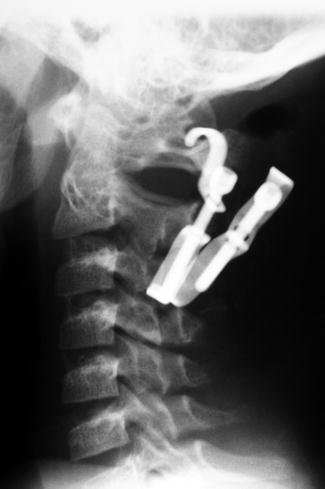
Fig. 10.2
Dislocation of Halifax clamps
C1-C2 Trans-articular Screw Technique
This technique, described in 1979 by Magerl [22] gained wide acceptance in the following years, being the most effective technique to stabilize C1-C2 [18], especially if combined with posterior wiring or clamps [31]. This technique can be used also in cases where there is an interruption of the posterior arch of C1 but requires a good alignment of the axis.
The patient is placed in the prone position in a three-points head holder: a horse-shoe head holder can also be used, but, in this case, is more difficult to obtain the optimal alignment of the axis. With an external K-wire the ideal trajectory of the screws is identified before the skin incision [35]. The entry point for the drill, in most cases, lies laterally to the spinous process of T1 or T2. The skin incision is on the midline from C0 to C3 and a careful dissection of the muscles is performed. During this step is important to maintain the midline to avoid bleeding from the muscles which are easily detached from the C1 and C2 posterior aspect, especially in young subjects. There is no need to extend dissection too far laterally, but identification of the C2-C3 joint is mandatory. Two small incisions are then made and two guide tubes are placed along the ideal trajectory from the T2 level up to the C2-C3 joint. The direction is checked with X-rays and the entry point on C2 is identified: it lies just 3 mm medially and superiorly to the center of the C2-C3 joint. After decortication of the dorsal aspect of the joint a guide K-wire is drilled under x-ray control with a sagittal direction toward the anterior C1 tubercle and with a lateral medial inclination of about 0–10°. If it is not possible to obtain a perfect C1-C2 alignment the trajectory should be a little superior to the anterior tubercle. The drilling is stopped 3–4 mm before reaching the anterior tubercle, preventing penetration of the retropharingeal space and a cannulated screw is then screwed on the K-wire. A special attention must be paid to avoid the advance of the K-wire while the screw is positioned. Some systems have also the possibility to connect two hooks, embracing the posterior arch of the atlas, to the screws, creating a very strong stabilization of the axis (Ulrich Company, Ulm, Germany) (Fig. 10.3a, b). Bone autograft or allograft is finally positioned between C1 and C2. If any doubt arises, a small spatula can be inserted in the C1-C2 joint, after dislocation of the C2 nerve root to check the presence of the screw crossing the joint.
Fig. 10.3
(a) Transarticular C1-C2 fixation and C1 posterior arch clamps. Operative field. (b) Transarticular C1-C2 fixation and C1 posterior arch clamps. Post-operative X-rays
The main problem of this technique is the risk of lesions to the vertebral artery [39]; a pre-operative CT scan with reconstruction should always be performed to investigate the course of vertebral artery. Some studies have shown that anomalies of the vertebral artery anatomy or a large vertebral artery groove are present in more than 20 % of the patients [21, 27]. In these cases there are two options: to change technique or to perform an unilateral transarticular fixation .
C1 Lateral Mass Screws and C2 Pedicle Fixation
This technique was first described by Goel and Leheri in 1994 [11, 13], but gained popularity after its reappraisal by Harms and Melcher [16] some years later. The main advantage of this method is that the integrity of the posterior arch of C1 is not needed and also alignment of the axis is not necessary. With this technique a reduction and alignment of the C1-C2 complex can be obtained also in many cases considered non reducible at the pre-operative studies (Fig. 10.4a–c). At the same time the technique allows good results in terms of primary stability [6] and later fusion [13]. The technique is suitable also in mild cases of basilar invagination: by distraction of C1 and C2 the dens is pulled downward, (or the skull is pushed upward) releasing compression on the ventral aspect of the brain stem , so that transoral decompression can be avoided [15].