(1)
Chefarzt Wirbelsäulen Chirurgie, Behandlungszentrum Bewegungsapparat, Universitätsspital, Basel, Switzerland
The posterior exposure of the atlantoaxial joints may be indicated for insertion of transarticular screws at C1–C2 for bone grafting of the joints themselves, for exact evaluation of the congruency of the atlantoaxial joints (e.g., for reduction of a rotatory dislocation or an unstable Jefferson fracture), or for the resection of small tumors of the lateral mass of the atlas.
This chapter describes the exposure of the atlantoaxial joints and the posterior aspect of the lateral masses of the atlas. We present the transarticular screw fixation technique for C1–C2 as described by Magerl et al. [1], and use the example of an open reduction and internal fixation of a Jefferson fracture to illustrate the possibilities of this approach.
Positioning the Patient
The patient is intubated using the endoscopic technique and placed prone on the operating table, with the head positioned in a head holder (Fig. 39.1). Halo traction may be used to allow easier open reduction of a Jefferson fracture or to stabilize an unstable situation; however, the author does not use halo traction. Using lateral image intensifier control immediately after positioning the patient in the prone position, the atlantoaxial reduction is checked. If anterior subluxation of C1 on C2 has occurred during positioning, the head is lifted together with the head holder, using fluoroscopic control to monitor reduction. This maneuver will reduce C1 on C2. The upper cervical spine is then flexed as much as possible by tilting the head holder, still under lateral fluoroscopic control, while the lower cervical spine is only slightly flexed. Flexion of the upper cervical spine is important to allow correct placement of the transarticular screws for C1–C2.
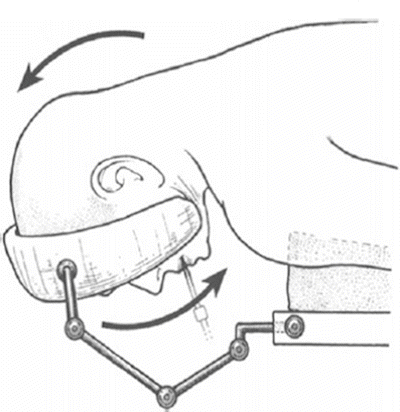

Fig. 39.1
The patient is placed prone on the operating table, the head maintained in a head holder. The occipitocervical joints are flexed as much as possible but the lower cervical spine is only slightly flexed
Surgical Exposure
Approach (Figs. 39.2, 39.3)
A midline incision is performed from the protuberantia occipitalis externa to the tip of the spinous process of C5. The musculature is divided in the midline down to the tips of the spinous processes and down to the occiput. The spinous process of C2 is prominent and easy to find. The musculature attached to it is cut at its insertion with electrocautery. To allow adequate exposure of the atlas, the musculature attached to the occiput must be retracted laterally, from the protuberantia occipitalis externa down to the vicinity of the foramen magnum; this is done using a Cobb elevator while an assistant is holding the head to prevent undue motion at C1–C2. Bleeding from the bone is controlled with bone wax. Spreading of the musculature with sharp retractors allows for best visualization and also minimizes blood loss. The posterior arch of the atlas is located in the depth between the occiput and the spinous process of C2, both of which are already exposed. The posterior arch of CI is found by gently dividing the soft tissues between the occiput and the spinous process of C2 until bony contact is obtained. Starting in the midline, the muscle attachments to the posterior arch of the atlas are gently cut directly on the bone using either a knife or electrocautery. The posterior arch of the atlas is exposed subperiosteally on a width of approximatively 2 cm. Although careful exposure of the midportion of the posterior arch is without danger, care must be taken when reaching the lateral part because the vertebral artery runs over the cranial part of the arch and enters the spinal canal behind the lateral mass of the atlas. The superior part of the posterior arch is therefore only prepared in the midportion and only if a wire loop must be passed around it later in the procedure.
The spinous processes, the laminae, and the articular processes of C2 and C3 are now exposed subperiosteally without destroying the joint capsules of C2–C3. Consequent soft tissue retraction helps for adequate exposure; the muscles are meticulously retracted with sharp retractors to allow for best visualization of the operative field.
Subperiosteal Dissection of the Atlantoaxial Joints
Using a small sharp elevator (4 to 5 mm wide), the cranial surface of the lamina of C2 is exposed (Fig. 39.2). Along this crest, the elevator is gently brought anteriorly and the soft tissues detached, still staying strictly subperiosteally and exposing the isthmus of C2. The soft tissues located cranial to the elevator contain the nerve root C2 as well as the surrounding venous plexus. These structures are gently retracted with a slightly curved dissector exposing the isthmus, while dissection is carried on further anteriorly, still remaining strictly on the crest and subperiosteally. In the anterior part of the isthmus, an upward step is felt corresponding to the slope located just behind the superior articular facet of C2. The joint capsules are thin and can be opened using the elevator. By turning the elevator upward, the posterior aspect of the lateral mass of the atlas can be exposed subperiosteally by slightly scratching the bone with the sharp elevator. The capsule can be elevated with a dissector, exposing the joint (Fig. 39.3). If desired, a K-wire can be inserted into the posterior aspect of the lateral mass of the atlas under direct vision (Fig. 39.4a). The K-wire should be slightly flexible, for example, 1.6 mm in diameter. When retracting the soft tissues with this K-wire, the cartilage of the atlantoaxial joints can be seen (Fig. 39.4b). A small dissector can also be placed lateral to the lateral mass, remaining inside the joint capsule and exposing the posterolateral aspect of the joint.
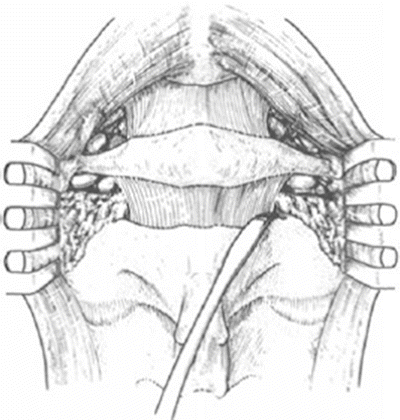
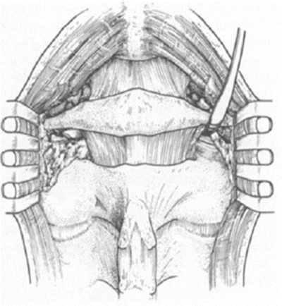
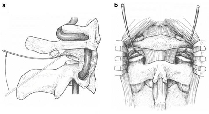

Fig. 39.2
After subperiosteal exposure of the occiput, posterior arch of the atlas, and posterior elements (spinous process, lamina, and articular masses) of C2 and C3, the cranial part of the lamina of C2 is exposed and followed subperiosteally toward the isthmus, staying on the crest of the lamina

Fig. 39.3
The soft tissues cranial to the elevator contain the nerve root C2 as well as its surrounding venous plexus. These elements are gently retracted with a dissector. Once the posterior aspect of the atlantoaxial joint has been reached, the capsule can be opened and retracted with the same dissector, exposing parts of the posterior aspect of the atlantoaxial joint

Fig. 39.4
(a) To allow better visualization of the atlantoaxial joint, a K-wire may be driven into the posterior aspect of the lateral mass, the K-wire being inserted underneath the joint capsule. By elevating the K-wire, the soft tissues containing the nerve root C2 are retracted cranially, allowing visualization of the joints. (b) Posterior view of both atlantoaxial joints after the K-wires are retracted cranially
During exposure of the isthmus, the venous plexus surrounding the nerve root of C2 may be damaged with venous bleeding as a consequence. This hemorrhage may be stopped by introducing a small amount of collagen between the venous plexus and the isthmus of C2; however, care must be taken not to exert pressure on the dura. The best prophylaxis for such a bleeding is to stay subperiosteally during the preparation and to retract the nerve root of C2 with the surrounding plexus using great care.
Exposure of the Posterior Aspect of the Lateral Masses of C1
For better visualization of the posterior aspect of the lateral masses of C1, it may sometimes be necessary to also expose it cranially, starting from the posterior arch of the atlas (for example, for removal of a small tumor in the posterior part of lateral mass or for reducing an unstable Jefferson fracture). The caudal aspect of the posterior arch of the atlas is then exposed subperiosteally on both sides until the junction to the lateral masses is reached, using sharp dissectors or an elevator. Care is taken not to expose the cranial aspect of the arch where the vertebral artery could be damaged. Once the posterior aspect of the lateral mass has been reached, the nerve root of C2 is completely freed from its attachments to the lateral mass, allowing visualization of the posterior aspect of the lateral masses and of the atlantoaxial joint both cranially and caudally. Theoretically, the nerve root C2 could be cut and ligated, if absolutely necessary for adequate exposure.
Transarticular Screw Fixation of C1–C2
Indications
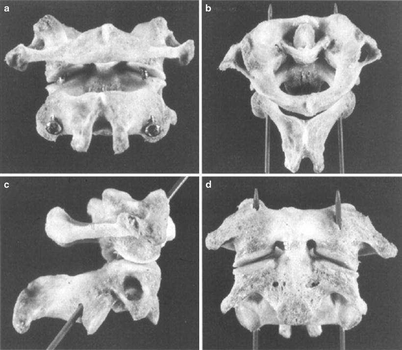
Transarticular screw fixation of C1–C2 (Fig. 39.5) is always used in combination with a fusion (see following) and may be indicated in the following situations:

