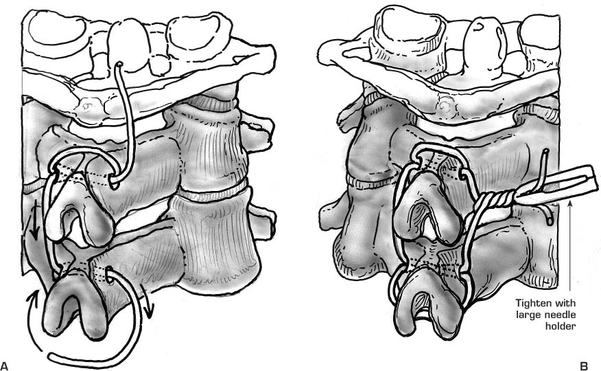
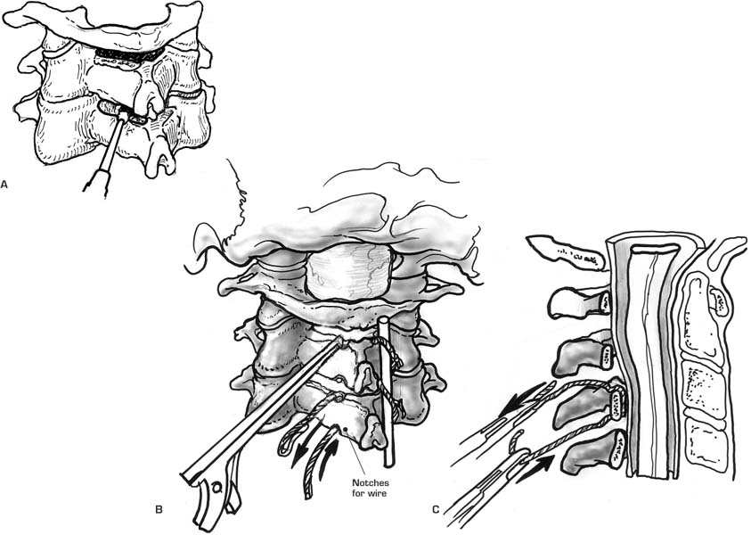
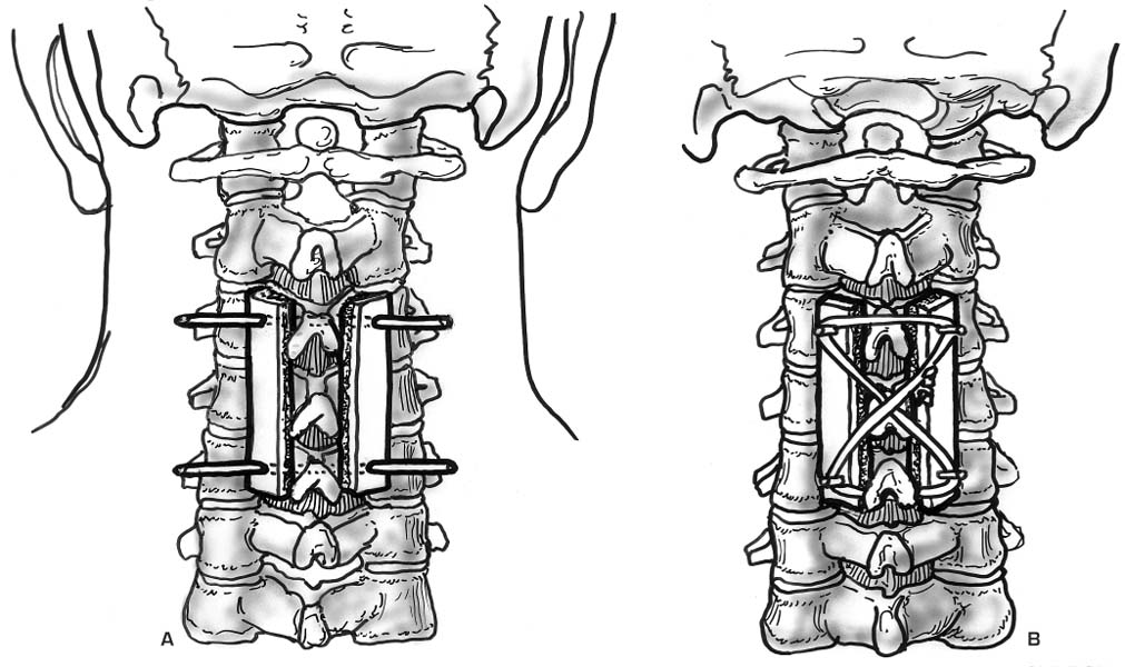
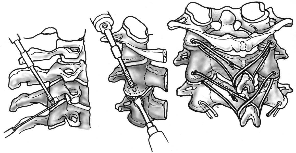
11 Posterior Wiring Techniques of the Spine Wiring techniques of the spine affords semirigid stabilization of the vertebral elements. It is often used as the primary method of fixation in the cervical spine when combined with a rigid external orthosis. Wiring techniques of the thoracolumbar spine are often used in conjunction with other modes of internal fixation (e.g., rods) to allow rigid segmental stabilization. If the spinal elements are excessively loaded or the posterior elements are osteoporotic, wire stabilization alone may not afford adequate immobilization even with supplemental external brace or cast application. Several techniques have been described to stabilize the occipital-cervical/upper cervical spine. Occipital-cervical and upper cervical spine wiring techniques include the technique of Wertheim and Bohlman (occipitalcervical) and Gallie’s and Brooks‘ methods. Lower cervical wiring techniques include the Rogers, Bohlman, and Dewar methods. Modifications and adaptations of each method have also been described. Posterior occipital and lower cervical wiring procedures are performed through a midline incision with careful dissection through the fascial raphe to avoid muscular bleeding. This allows for subsequent exposure of the intended occipital and posterior cervical elements in a subperiosteal manner. To avoid excessive vascular bleeding in the upper cervical region between the C1 and C2 articulation, the thin-walled cavernous venous plexus is gently elevated at its medial margin with a small patty. Taking care to avoid disruption of this plexus is important due to its lack of discrete endothelial channels, as this plexus represents a confluence of venous sinusoids. A bipolar forceps is useful if a small venotomy is encountered. During the exposure of the subaxial spine, only the lateral margin of the lateral masses should be exposed, taking care not to go beyond this boundary, especially in an anterior direction. One may encounter dense arterial and venous networks in this area that are difficult to control without temporary packing. At the completion of the surgical exposure, any manipulative reduction may be performed followed by placement of internal fixation (wires) and bone grafting. 1. Occipitocervical instability 2. Odontoid fracture in the setting of C1 posterior ring incompetence 1. Arnold-Chiari malformation requiring a suboccipital decompression 2. Foramen magnum stenosis requiring significant suboccipital decompression 1. Achieves immediate semirigid fixation of the occipital cervical junction 2. Does not require the passage of wires through both cortices of the skull and is easily modified to address important anatomical variables Requires rigid external orthotic immobilization. Occipital Wiring: At a point 2 cm above the rim of the foramen magnum, a high-speed diamond bur is used to create a trough on either side of the occipital crest or inion. This allows the formation of a central bony ridge. With a towel clip or tenaculum, a hole is made through this bony ridge involving only the outer bony calvarium of the skull. A 20-gauge wire is then passed through the hole. Another 20-gauge wire is passed in a sublaminar manner under the arch of the atlas, and an additional wire is passed through a drill-hole in the base of the spinous process of the axis and looped around its inferior border. Therefore, on each side of the spine there are three separate wire ends, which are utilized to secure separate corticocancellous, longitudinally oriented bone struts. The posterior iliac crest is exposed and the curved portion of the crest, of the appropriate length and width, is harvested and divided to cover each side of the intended fusion area. The convex surface of each tricortical bone graft is decorticated to allow cancellous on cancellous (decorticated posterior occipital-cervical elements) bony contact. Three drill holes are then placed in each graft for wire passage. The grafts are then anchored in place on both sides of the occipital-cervical junction. Additional cancellous bone is packed between the two grafts as needed (Wertheim and Bohlman, 1987). A semirigid form of stabilization often requiring rigid external orthosis wear for 2 to 3 months. Care must be taken to avoid inner calvarium penetration during occipital drilling or wire passage. Patients are immobilized in a cervicothoracic orthosis or halo vest for 2 to 3 months. 1. C1-C2 instability 2. Odontoid fracture Posterior (C1 or C2) element deficiency Technically simple 1. Less biomechanically stable than the Brooks technique (see below) 2. Suboptimal stability in extension, translation, and rotation At the completion of exposure of the posterior cervical elements, the soft tissue attachments to the C1 lamina (occipital atlantal and atlantoaxial membranes) are elevated in a subperiosteal manner. A Woodson probe is placed beneath the C1 lamina in a caudad and cephalad direction to make sure it is free of any soft tissue attachments. A doubled-over 16- or 18-gauge wire is then shaped in a semilunar fashion and gently passed in a caudad to cephalad direction beneath the C1 lamina (Fig. 11–2A). A corticocancellous block of autologous bone is harvested from the iliac crest, and a notch is created at its inferior border to straddle the C2 spinous process. The upper margin of the graft is positioned dorsal to the C1 arch (Fig. 11–2B). The leading edge of the wire loop is then brought over the graft and opened to loop around the C2 spinous process. The free wire ends are then brought around the sides of the graft and tied to each other over the dorsal surface of the bone graft (Fig. 11–2C). Care must be taken not to posteriorly displace the C1 vertebral body during wire manipulation or tightening. This mechanical construct weakly resists translation, rotation, and extension compared with the modified Brooks technique for C1-C2 fixation (White and Panjabi, 1978). The patient is usually kept in a cervicothoracic orthosis or halo vest for approximately 2 to 3 months to allow for bony healing. Early after surgery the patient is encouraged to carry out general isometric neck muscle exercises. 1. C1-C2 instability 2. Odontoid fracture Figure 11–1 Figure 11–2 Figure 11–3 Figure 11–4 Figure 11–5 Figure 11–6 Figure 11–7 Figure 11–8 Figure 11–9 Figure 11–10 1. Spinal stenosis 2. Posterior (C1 or C2) element insufficiency 1. Technically simple 2. Greater resistance to translation, rotation, and extension than the Gallie fusion (White and Panjabi, 1978). Risk of neural injury with C1 and C2 sublaminar wire passage
Goals of Surgical Treatment
Surgical Approach for Posterior Occipital and Cervical Wire Application
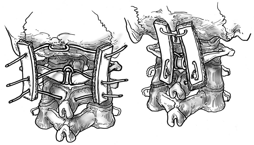
Occipital-Cervical Spine Technique of Wertheim and Bohlman (Fig. 11–1)
Indications
Contraindications
Advantages
Disadvantages
Procedure
Pitfalls
Complications
Postoperative Care
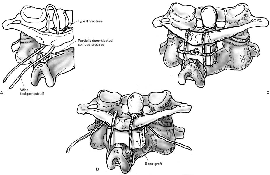
Upper Cervical Spine Modified Gallie’s Technique (Gallie, 1937, 1939) (Fig. 11–2)
Indications
Contraindications
Advantages
Disadvantages
Procedure
Pitfalls
Complications
Postoperative Care
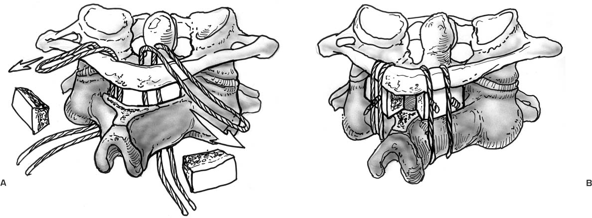
Modified Brooks Techniques (Fig. 11–3)
Indications
Wertheim and Bohlman technique for occipitocervical fusion. The occiput, C1, and C2 are fused with midline wires and a pair of bone struts.
(A–C) Modified Gallie technique. A bone graft is secured over the posterior arches of C1 and C2 by passing a single wire under the arch of C1 and looping it over the spinous process of C2.
Modified Brooks fusion. (A) C1 and C2 are fused by placing bone wedges posteriorly in between their lamina. (B) Wires are then passed from below under the lamina of C2 and C1, securing the two segments and bone graft together.
Rogers technique. Two adjacent cervical spinal segments are secured by the passage of a looped interspinous process wire.
(A,B) The Bohlman’s triple wire technique is similar to the Roger’s technique except for the addition of spinous process wires that function to secure two cortical cancellous bone graft stents over the posterior elements of the intended fusion area.
(A–C) Subaxial cervical sublaminar wire technique. Sublaminar wires are carefully passed under the lamina of each segment only with direct visualization of the dura to prevent neural compression.
Dewar fusion. (A) The cervical vertebrae are initially decorticated and then stabilized with Steinmann pins. (B) These are then passed through both the vertebrae and adjacent corticocancellous strut-grafts.
Oblique facet wiring. A wire is passed through a drill hole in the inferior cervical articular process. The wire is then passed through the spinous process of the inferior vertebra to secure the vertebral interspace.
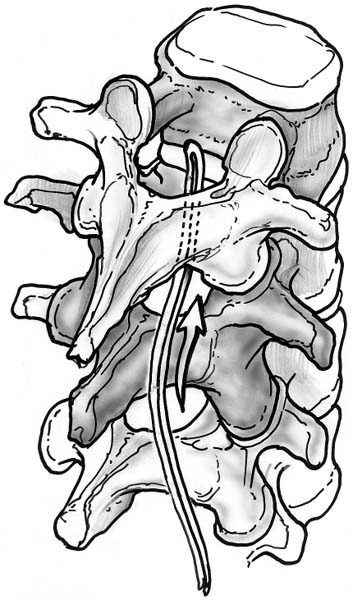
Thoracolumbar sublaminar wire passage. The wire utilized is often a 16- or 18-gauge wire looped on itself to allow the smooth looped cord to be the leading surface during passage.
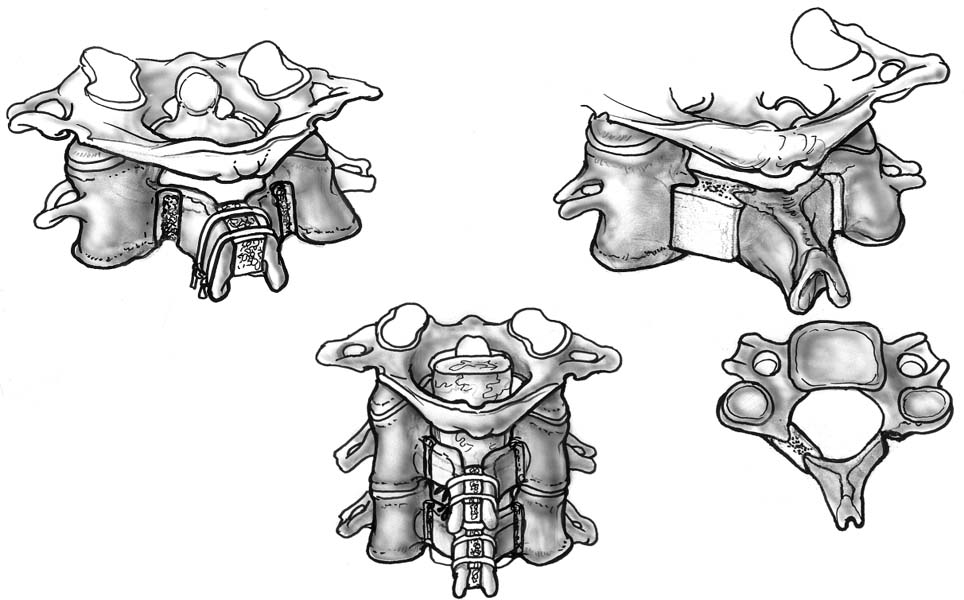
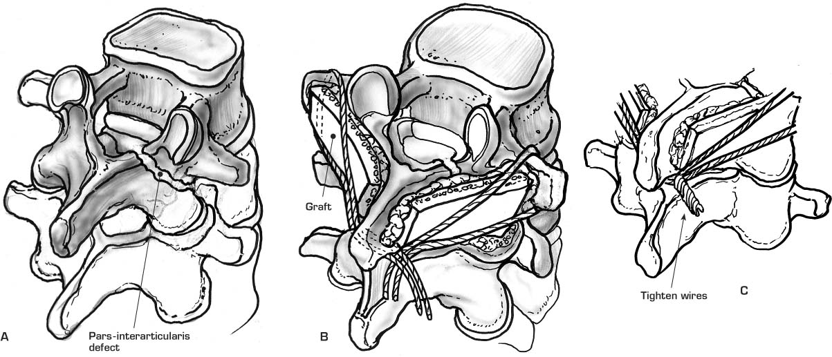
(A–C) Scott technique. A bone graft is secured in the decorticated pars interarticularis defect by looping a wire around the transverse process and spinous process of the respective vertebrae.
Contraindications
Advantages
Disadvantages
Procedure
Stay updated, free articles. Join our Telegram channel

Full access? Get Clinical Tree


