Schematic representation of the lines of electrical force that radiate from the negative electrode (cathode) for various configurations. In the case of unipolar configuration (a), where there is a single negative electrode (cathode) and a positive electrode (anode) a far distance away (in electrical terms), as when the implanted neurostimulator metal case is used as the positive electrode, the lines of electrical force radiate out in all directions. In the case of bipolar configurations (b and c), where the negative electrode is near the positive electrode (on the same DBS lead), the lines of electrical force radiating out of the negative electrode are bent or pulled toward the positive electrode. The force or intensity of the electrical force can be conceptualized as the number of lines of electrical force that pass through a specific region of space, in this case represented by the box. As can be seen, as the box moves away from the negative electrode (a), the lines of electrical force passing through the volume represented by the box get smaller, representing a reduction in the strength of the electrical field. In the case of the bipolar configuration, the geometry of the electrical field is more complicated. As can be seen in the wide bipolar configuration (b), there are a greater number of lines of electrical force further away from the line that connects the negative and positive contacts, as represented by the number of lines of electrical force passing through the volume represented by the shaded box compared to the narrow bipolar configuration. In the case of a narrow bipolar configuration (c), it is as though the closer positive electrode is pulling a greater number of lines of electrical force closer to the line that connects the negative and positive electrodes. This acts to pull them in from the space around the DBS lead, thereby reducing the intensity of the electrical fields at distances from the line connecting the negative and positive electrodes.
The basic unit of information in the brain
Although neurons receive information in the form of synaptic inputs mediated by neurotransmitters and neuromodulators or in the form of electric gap junctions, the final product of neuronal processing is encoded in the sequence of action potentials that are conveyed down the axon to the next neuron (Figure 5.2). (There are a few types of neurons that do not use the all-or-nothing action potentials but rather a graded potential, such as the retinal bipolar cells.) Also, as described above, the main mechanism of action of DBS probably relates to the action potentials generated in response to the DBS pulse. Consequently, it is worthwhile to understand the nature of the action potential.
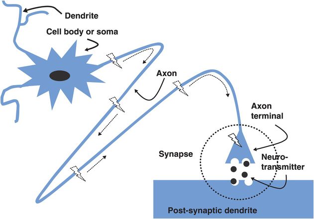
The neuron, consisting of a cell body, dendrites, axon, and axonal terminals leading to synaptic contacts on the next neuron. Once the neuronal membrane voltage reaches a depolarization threshold at the axon hillock (the beginning of the axon), an action potential is initiated (lightning bolt), which then proceeds down the axon to the synaptic terminal. There the action potential depolarizes the axon terminal, causing the release of neurotransmitters that initiate a change in the neuronal membrane potential in the dendrites or cell body of the next neuron.
An action potential could be considered analogous to an electrical spark or the light flash of a light bulb, which are, in effect, flows of electrical current. In the case of an electrical spark or the flash of light, the flow of electricity is mediated by electrons, but in the case of a neuron, the electrical current is mediated by the flow of positively and negatively charged ions, such as sodium (Na+), potassium (K+), chloride (Cl−), and calcium (Ca2+).
In order for there to be a flow of electrical current, there must be some force to push the electrical current. Neurons create this force by creating an electrical potential across the cell membrane of the neuron. Neurons create a relatively greater positive charge outside the neuronal membrane and a relatively greater negative charge inside the neuron. The difference between the positivity outside the neuron and the negativity inside the neuron is the membrane potential. Neurons create the membrane potential by pumping more positive ions, for example Na+, out compared to the number of positive ions that are pumped in, for example K+ (Figure 5.3). Note that this energy-dependent pumping also creates a concentration gradient, with relatively more Na+ outside the neuron and more K+ inside the neuron. This difference in concentration creates a force that, if allowed to act, would drive Na+ ions into the neuron and K+ ions out of the neuron. This force is the origin of the force that drives electrical current typified by the action potential.
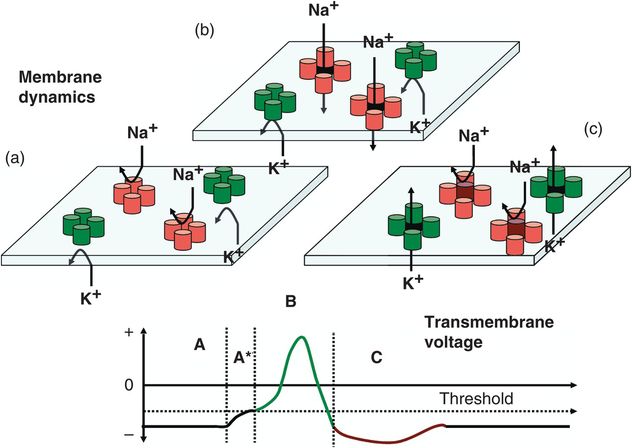
Schematic representation of one example of mechanisms generating an action potential. During the resting phase, the neuron pumps Na+ ions out of the cell and K+ ions into the cell. Relatively more Na+ ions are pumped out compared to the number of K+ ions that are pumped in. This results in the interior of the neuron having a negative voltage relative to the outside of the neuron (lower figure, segment A). Also, the difference in concentrations results in a driving force, pushing Na+ inside and K+ out. However, the flow of these ions is blocked at rest because the channels that allow the ions to move across the membrane are closed. (a) In response to excitation, the membrane voltage rises (lower figure, segment A*). Once a threshold is reached, the Na+ channels open, allowing Na+ ions to enter the neuron (b) and causing the neuronal membrane to become more positive (lower figure, segment B). Then the Na+ channels become inactivated, thereby blocking further Na+ ions from entering the neuron. Shortly afterwards, the K+ ion channels open, allowing K+ ions to flow out of the neuron (c), thus causing the membrane potential to become more negative and reversing the effects of the previous flow of Na+ ions (lower figure, segment C). In fact, the efflux of K+ ions temporarily makes the neuronal membrane relatively more negative than when the neuron is at rest, resulting in a hyperpolarized state. The pumping mechanisms described above then restore the normal neuronal membrane potential at rest.
For a spark to occur or for the light bulb to flash, a switch must be closed. Closing the switch allows electrons to flow through a gap to produce an electrical spark or to flow through the wire in the light bulb, which heats up to produce the flash of light. In the case of the neuron, the switch is in the neuronal membrane. In the electronic switch, a gap is closed between two conductors to let electrons flow through. In the neuron, channels in the neuronal membrane open to allow ions to flow through (Figure 5.3).
In the case of an electrical spark or the light bulb, the electronic switch would need to be pushed closed to allow electrons to flow. In the neuron, the channels open to allow ions to flow or close to prevent ions from flowing, depending on the neuronal membrane potential. At rest, the neuronal membrane potential may be −60 to −70 millivolts (mV). If the neuronal membrane potential decreases by becoming less negative (or more positive) it is depolarized. If the depolarization reaches a threshold the channels open allowing ions, such as Na+ and K+, to flow, generating an electrical flow or current. The time course of the Na+ channels opening is much faster than the K+ channels. The result is that Na+ enters the neuron and the inside of the neuron becomes even less negative and finally becomes positive, transiently.
The influx of Na+ is limited. When the neuronal membrane potential continues to decrease, becoming less negative, the Na+ channels inactivate, preventing further flow of Na+ ions and preventing the inside of the neuron from becoming more positive. The K+ channels continue to be open and more positive ions leave, making the inside of the neuron more negative and thereby reversing the change in the neuronal membrane potential initiated by the flow of Na+ ions into the neuron. When the neuronal membrane becomes more negative than the resting condition, the neuron is hyperpolarized. This hyperpolarization takes the neuronal membrane potential further away from the threshold, making it less likely to generate an action potential. This period of decreased excitability is called a relative refractory period. Also, the hyperpolarization deactivates the Na+ channels, and until the Na+ channels are reactivated, the neuron cannot generate an action potential. For the DBS pulse to initiate an action potential, the DBS pulse must depolarize the neuronal membrane, that is, reduce the difference between the relative positivity outside the neuron and the relative negativity inside the neuron. The DBS pulse can do so by dumping negative charges onto the outside of the neuron. The electrons exiting the DBS electrode during the DBS pulse are converted to negatively charged ions. A brief mention of depolarization blockade should be made because it has been offered as a potential mechanism of action of DBS. If the neuronal membrane is made less negative, or depolarized, but kept below the threshold for an action potential, Na+ channels begin to close, thereby reducing the ability of the neuron to generate an action potential. However, there is considerable empirical evidence3 as well as information from computational modeling12 suggesting that depolarization blockade is not likely to be a mechanism of therapeutic action.
The key in DBS device programming will be to control the spatial distribution and intensity of the electrical field generated by the DBS pulse that drives the negative ions onto the neuron.
The electronics of DBS
The key to effective DBS is to control the number and spatial extent of neural elements in which action potentials are generated. Note that the number and spatial extent are not synonymous. For example, as will be demonstrated subsequently, a unipolar configuration – in which there is a single negative electrode (cathode) and the metal case of the implanted neurostimulator acts as the positive electrode (anode) – may generate a less-intense but larger electrical field and activate fewer neural elements than a bipolar configuration, which though smaller in extent, is more intense.
The activation of neural elements will depend on the concentration of negative charges generated at the negative electrode (cathode), which will depend on how many electrons are being dumped by the cathode per unit time over the time of the DBS pulse. The measure of the number of electrons per unit time is electrical current and it is measured in amperes – typically in DBS, in milliamps. The total amount of electrons deposited is measured in coulombs, in DBS as microcoulombs. The force that drives the electrons out of the DBS negative electrode (cathode) is the electromotive force (EMF) and is measured in volts. The amount of electrical current delivered will depend on the amount of electromotive force, or voltage, and the resistance to the flow of electrical current. In the case of DBS, the resistance varies because the electrical current is not constant for each DBS pulse; rather, the current goes up and down rapidly. The resistance in such situations of fluctuating electrical current is called impedance and is measured in ohms.
Note that the impedance of the electrode is a function of the frequency components within the DBS pulse and not the frequency at which the pulses are delivered.
The relationship between electrical current (I), electromotive force (E), and impedance (R) is given by Ohm’s law: I = E/R.
This relationship is fundamentally important in DBS because the impedances, electromotive force (volts), and electrical current can vary between patients, between different stimulation parameters, with different configurations of active electrodes, and with the type of neurostimulator used. For example, the electrical current delivered by constant-voltage neurostimulators, which are designed to deliver a constant voltage regardless of the amount of electrical current, will be different because of differences in impedance – despite the same voltage. Constant-current neurostimulators automatically adjust the voltage as necessary for different impedances to maintain the same electrical current. The distinction is critical, as it is the electrical current delivered by the DBS pulse that determines the activation of neural elements. Also, it is the electrical current that figures in DBS safety and not the voltage.
Understanding these concepts often is facilitated by considering an analogy between the flow of electrons and the flow of water. Consider a water reservoir on a tower with a hose exiting from the bottom. The amount of water in the reservoir represents the stored electrical charges in the neurostimulator battery. One can think of electrical charge as the number of positive or negative ions or the number of electrons. The hose represents the DBS electrodes through which the electrons would flow. The water pressure in the hose depends on the height of the water reservoir, which would be analogous to the electromotive force or voltage. Higher towers are associated with higher water pressures and, by analogy, voltages. The increased height of the water tower or higher voltage results in higher flows of water or electrical current, assuming the impedance (resistance) is constant. The amount of water delivered through the hose would correspond to the electrical charge measured in microcoulombs. The amount of water per unit time from the hose would correspond to the electrical current in milliamps. As common experience shows, smaller diameter hoses result in more resistance (impedance) to the flow of water. In this case, the diameter of the hose would be inversely proportional to the impedance in the DBS system by analogy.
Manipulations of the water analogy help to understand the manipulations of the electronics in the DBS system. Picture the water tower at one height. There will be a certain hydrostatic force that will cause water to flow from the hose. Now picture the water tower rising to a new height. This will result in more force to move the water out of the hose. The increase in the height of the water tower would correspond to increasing the voltage. The result will be increased electrical current and deposition of more electrical charges during the stimulation pulse. Now consider the situation where the height of the water reservoir is constant but the diameter of the water hose increases, thereby reducing the impedance. The result will be a greater flow of water and more water delivered. By analogy, if the voltage remains constant but the impedance is reduced, there will be greater electrical current from the DBS electrode and greater amounts of electrical charges deposited in the brain. If the voltage is constant and the impedance increased, there will be less electrical current flowing into the brain.
As previously stated, the electrical current, rather than voltage, has greater influence in causing an action potential in the neural elements. However, the actual factor is the electrical charge density, which is related to the rate by which electrical charges are injected into the brain (milliamps), the time period that the current flows (pulse width in DBS), and the surface area of the electrode. The relationship is given by the following equations.
For constant-current neurostimulators:
Related posts:
 Patient selection
Managing essential tremor patients treated with deep brain stimulation
Patient selection
Managing essential tremor patients treated with deep brain stimulation
 Managing dystonia patients treated with deep brain stimulation
 Managing epilepsy patients treated with deep brain stimulation
 New techniques for deep brain stimulation lead implantation
 Managing Parkinson’s disease patients treated with deep brain stimulation
Stay updated, free articles. Join our Telegram channel

Full access? Get Clinical Tree


