, Damien Gervasoni1 and Catherine Vogt2
(1)
Lyon Neuroscience Research Centre CNRS UMR 5292–INSERM U 1028, Université Claude Bernard Lyon 1, Lyon, France
(2)
Université Claude Bernard Lyon 1, Lyon, France
6.1 Generalities
Stereotaxic surgery is used in combination with other diverse techniques necessary for addressing the specific objectives of a proposed study. These techniques include experimental procedures in vivo for activating or inactivating brain structures or transmitter systems, permanent selective lesioning, functional neuroanatomy using tracers, and acute or chronic measurements or recordings. The principal aspects of some of these techniques are described below.
Stereotaxic neurosurgery can be used in lesioning (damaging, depleting, or ablating) a structure or transmitter system:
By electrolysis (Duncan et al. 1975)
By transection (Milner and Amaral 1984)
By radio frequency (King1991)
By injection of excitotoxins such as ibotenic acid (Jarrard 2002), 6-hydroxydopamine for dopaminergic neurons (Rotman and Creveling 1976; Kostrzewa 1995, Kostrzewa and Brus 1998; Schwarting and Huston 1996, 1997; Glinka et al. 1997; Centonze et al. 1999; Blum et al. 2001), N-(2-chloroethyl)-N-ethyl-2-bromobenzylamine (DSP4) for noradrenergic neurons (Jonsson 1980; Fritschy and Grzanna 1991; Dudley et al. 1990; Kostrzewa 2009) and immunotoxins such as 192 IgG-saporin for cholinergic systems (Wiley 1992, 1997, 2001; Schliebs et al. 1996; McGaughy et al. 2000)
By global or focal ischemia using devascularization, photo-irradiation, vessel occlusion, or vasoconstrictive agents (see Livingston-Thomas et al. 2013 and references therein)
Stereotaxic neurosurgery can permit the temporary inactivation of a structure:
By microinjection of muscimol (GABA agonist), tetrodotoxin (TTX), or lidocaine (to block nerve conduction by reducing membrane permeability of sodium ions that occurs during depolarization) (Chen et al. 2000)
By microinjection of receptor antagonists of the target system (see Chap. 2)
Stereotaxic neurosurgery can be used in stimulating a CNS structure:
Electrically (nonselective activation of a heterogeneous population of neurons)
By microinjection of N-methyl-d-aspartate (NMDA) that stimulates neurons bearing NMDA receptors
By microinjection of receptor agonists of the target system (see Chap. 2)
By applying a light stimulus (laser) after transfection of modified gene sequences (e.g., channel rhodopsin-2; Buchen 2010)
Stereotaxic neurosurgery can be used when marking a CNS structure:
By retrograde labeling, e.g., with horseradish peroxidase (HRP) or fast blue (Milner and Amaral 1984)
By anterograde labeling, e.g., with Phaseolus vulgaris leukoagglutinin (PHA-L) or radiolabeled amino acids (Milner and Amaral 1984)
Stereotaxic neurosurgery is also used in making in vivo measurements of:
The concentration of extracellular neuromediators (by microdialysis and voltammetry; Li et al. 2006)
Electric potentials (by electrophysiology)
6.2 Insertion of a Guide Cannula
This technique is used when manipulating the activity of a structure in a conscious or anesthetized rodent in acute or chronic experimental situations. A unilateral implantation into the dorsal hippocampus is used here as an example.
The stereotaxic coordinates of the target are: AP, – 3.14; ML, 2.0; and DV, – 3.5 from the dura mater in the rat AP, – 1.8; ML, 1.5; and DV, – 2.4 from the dura mater in the mouse Guide cannula: stainless steel; 7 mm long; 0.3 mm internal diameter and 0.4 mm external diameter for both the rat and the mouse Anchoring screws: stainless steel; length 1.20 mm and diameter 1.85 mm
The unilateral implantation of the guide cannula is performed under general anesthesia. After having exposed the cranial surface and before trepanation, tissue retractors (see Fig. 5.3) are placed on either side of the cranial area of interest (Fig. 6.2a) and anchor screws are attached to the skull. For this, pilot holes with a diameter slightly smaller than that of the screw thread (ideally the screw’s core diameter) are drilled about 3 mm distant from the desired point of insertion of the cannula.
For most procedures in the rat, two or three screws are used. For the mouse, one or two are usually sufficient (Fig. 6.1). For proper insertion, care should be taken to leave a space of at least 1 mm between the screw head and the surface of the skull. Care should also be taken that the screws are not inserted so far as to touch the surface of the brain.
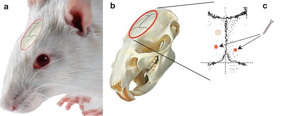

Fig. 6.1
Anchor screw placement. (a) Diagram showing the sutures of the cranial bones in the animal’s head. (b) Corresponding view of the animal’s skull. (c) Enlargement of the area corresponding to bregma and lambda reference points. The small dashed circle represents the location where the cannula will be inserted according to the coordinates for the dorsal hippocampus (in this example). The two red points correspond to the approximate locations of two anchoring screws
Once the anchor screws are inserted (Fig. 6.2), the stereotaxic coordinates are taken. The horizontality of the skull is carefully verified, the emplacement of the guide cannula pinpointed, and the insertion hole drilled (Fig. 6.3a).


Fig. 6.2
Mounting of the anchor screws following the preparation of the operatory zone. (a) Drilling of pilot holes for placement of the screws. (b) Image of anchor screws and a Terumo 25G hypodermic syringe needle showing their comparative sizes. (c) Insertion of anchor screws
6.2.1 Use of the Dental Drill and Handpiece
When the DV coordinate at the point situated on the vertical axis of the target has been surveyed and identified as described in the previous paragraph, the skull bone is drilled to access the dura. For this, a dental drill with drill bit and handpiece that have been previously sterilized are usually used. After the motor is turned on, the drill bit is applied to the skull surface applying just enough force to pierce the bone. This gesture should be carried out as quickly as possible to avoid generating heat caused by friction of the rotating bit, which can be further reduced by simultaneous irrigation with sterile saline. Particular care should be taken regarding the amount of force applied while drilling.
If too much force is applied and the bone is penetrated too deeply, there is a risk of damaging the dura and the surface of the cortex. After trepanation, the dura is delicately hooked using the tip of a small sterile hypodermic needle and then incised in a circular motion. The correct execution of this step is evident by the appearance of cerebrospinal fluid seeping out to the surface of the skull.
To facilitate the introduction of the cannula into the brain, the dura mater is perforated, or a small surface of it resected, using a sterile beveled syringe needle (Fig. 6.3b).
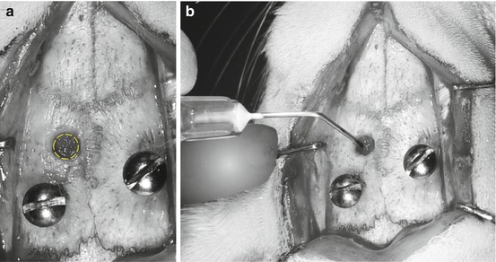

Fig. 6.3
(a) After the drilling of the insertion hole for the guide cannula. (b) Perforation of the dura mater using a sterile syringe needle to facilitate the insertion of the cannula guide
In order not to contaminate the cannula, it should be installed on the object carrier and inserted at the last moment, immediately after the dura mater has been perforated.
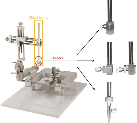

Fig. 6.4
Stereotaxic apparatus with various object (cannula, electrode, etc.) carriers that can be used for the type of implantation described above
After having installed a sterile cannula support or holder, which fixes the guide cannula to the object carrier (Fig. 6.4), it is imperative to check the verticality of its axis relative to the coronal and median planes before it is lowered (Fig. 6.5). If this is not done, the cannula could end up being inserted at an angle, thus missing its intended target.
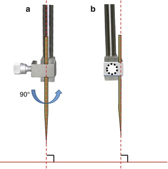

Fig. 6.5
Verification of the verticality of the instrument (e.g., cannula or electrode support) placed on the object carrier. (a) Coronal plane. (b) Median plane
When verticality has been verified, the object carrier is fixed to the vertical stereotaxic manipulator arm. The tracking of the arm should be carefully checked with respect to the graduations marked on its base. For convenience, it is preferable to align the arm with the principle graduation mark as reference. Any rotation of the arm necessary for this alignment does not affect its verticality. The validity of this reference point is indispensable if it becomes necessary to set an angle for inserting the cannula (Fig. 6.6). The guide cannula that will remain permanently implanted in the brain is then mounted onto the cannula support for insertion (Fig. 6.7).
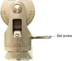
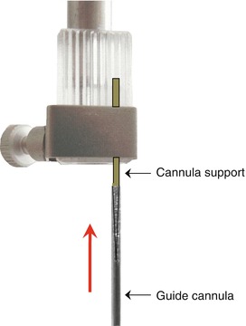

Fig. 6.6
Photograph showing the detail of the base of the vertical manipulator arm

Fig. 6.7
Diagram showing the mounting of the guide cannula (in the direction of the red arrow) onto the cannula support
Next, the guide cannula is carefully lowered according to the predetermined dorsoventral coordinates (in this example, DV = −3.5 mm for the rat, or DV = −2.4 mm for the mouse), checking that its displacement is smooth and even along the dorsoventral axis (Fig. 6.8). This step is very important: if the orifice of the guide cannula is not centered correctly with respect to the target coordinates, the cannula risks touching the bone at the edge of the insertion hole, deviating its verticality and compromising an accurate trajectory towards the target.
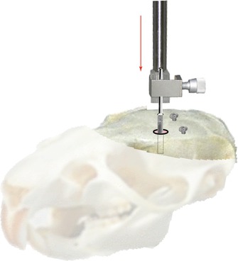

Fig. 6.8
Implantation of a guide cannula after placement of the anchor screws. Special attention should be paid to leave a space of about 1 mm distance between the head of the screw once fixed and the surface of the skull. The vertical red arrow indicates the direction followed by the object holder for the insertion of the guide
The rest of the surgical operation may have different experimental goals requiring specific procedures. Some of these are described in the examples that follow in this chapter.
The guide cannula and anchoring screws must be fixed solidly to the skull of the animal using dental acrylic cement (e.g., Paladur® powder and solvent, Heraeus Kulzer & Co. GmbH, or Unifast Trad® powder and solvent, GC America Inc.) that can flow easily and finely to coat the guide cannula and anchor screws (Fig. 6.9). The cement should have a fluid consistency so that it acquires a maximum hardness after it sets. It is recommended to use aliquots of resin powder and solvent in vessels that should be kept sterile on the instrument tray so as not to break the chain of asepsis during preparation of the cement.
Before applying the dental cement, it is recommended to first apply a self-curing adhesive resin such as (Super-Bond C&B®, Sun Medical Co., Japan), especially if the skull is to be subjected to high mechanical stress (Gervasoni et al. 1998, 2000) or if the implant is required to hold for several months. This type of adhesive exists in the form of a monomer powder and a liquid polymer that are mixed together with a few drops of catalyst just prior to use. For optimal adhesion, it is necessary to etch the bone surface by using a cotton swab to apply a solution, such as mixture B in the Super-Bond® kit, containing 10 % citric acid. Because of its corrosive property, care should be taken not to prolong the contact of this solution with the bone for more than half a minute and to carefully dry the bone surface after its preparation. The Super-Bond® resin is then applied using two brush techniques. In the case of a large area to cover, the technique of bulk mixing can be used, whereby the monomer and polymer are premixed together in a single vessel and the cement picked up and applied with the brush. For a quicker setting option, the brush-dip technique is used; this consists of first dipping the brush into the polymer solution, draining it of the excess and using it to pick up and apply the monomer powder. In both cases, the bone surface must first be well dried and free of any signs of hemorrhaging.
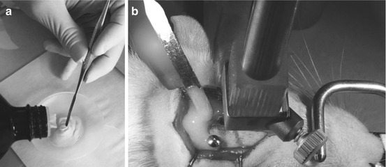

Fig. 6.9
Preparation of dental cement by bulk mixing (a) prior to its application onto the skull with a fine spatula. (b) Once the cement has entirely encircled the screws and cannula, it is necessary to wait several minutes to allow it to harden
When the cement is completely dried, the object carrier is raised slowly so that the guide cannula remains in place and visible on the skull (Fig. 6.10a). An obturator (“dummy” cannula) (Fig. 6.10b) is then inserted into the guide so that the latter does not become plugged during the postoperative recovery period (Fig. 6.10c).


Fig. 6.10
(a) Ascent of the object carrier, in the direction of the yellow arrow. (b) Guide cannula and its obturator (black arrow) shown beside a 25G Terumo hypodermic showing their comparative sizes. (c) Appearance of the guide cannula implant at the end of the procedure
It is useful to protect the guide cannula-obturator assembly with a plastic ring of the appropriate dimensions, which encloses the guide cannula but leaves enough space for the operator to easily manipulate the obturator. This protective collar is slipped around the guide cannula and encircled with a second layer of cement to fix it in place (Figs. 6.10c and 6.11).
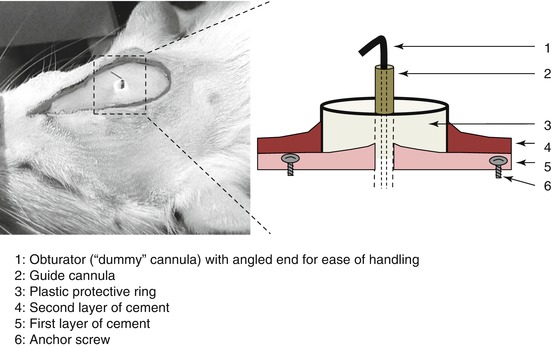

Fig. 6.11


The picture represents detail of the implanted guide cannula enclosed within the cement; the diagram is showing the different components of the material present on the skull surface at the end of the implantation procedure
Stay updated, free articles. Join our Telegram channel

Full access? Get Clinical Tree


