Fig. 13.1
(a) A double-decker pedicle screw. (b) A provisional rod is fixed on the two double-decker screws via the top-loading component. (c) A final rod is placed via the side-loading component while the provisional rod is in place
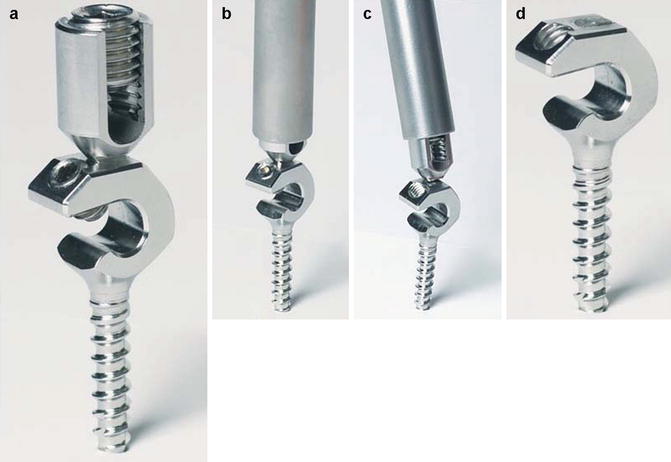
Fig. 13.2
(a) A double-decker pedicle screw. (b, c) The top-loading aperture of the screw is removed by a tube wrench. (d) The screw followed the top-loading aperture removal
A pedicle screw with a screw head that can receive two rods. The bone screw head includes two rod receivers. One receiver member is basic “U” shape (top-loading component) that extends from the top of the screw head to receive a provisional rod. Another receiver member has a basic “C” shape (side-loading component) that is inferior to the first receiver. The second receiver receives a final rod. There is a breakaway mechanism between the first and second apertures so that the first aperture can be removed while the final rod is fixed.
13.2.2 The Rod Link Reducer (Fig. 13.3)
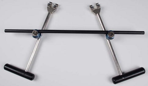
Fig. 13.3
A rod link reducer
The rod link reducer has a basic “H” shape that rigidly links and locks the provisional rods. The rod link reducer is a universal connecting link to provide a three-dimensional correction of the spinal deformity. It allows attachment to the rod at any orientation in the coronal, sagittal, and transverse planes so as to make a compression, distraction, derotation, and translation method.
The relative tools include (1) a screwdriver which is specially designed for the double-decker screw fixation (Fig. 13.4); (2) a long-arm tube wrench which is for a breakaway of the top-loading and side-loading apertures of the screw (Fig. 13.2); and (3) a final rod insertion wrench which is designed for the easy insertion of the final rod (Fig. 13.5).
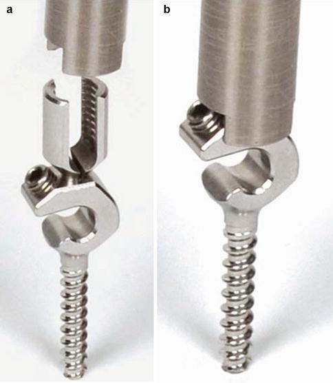
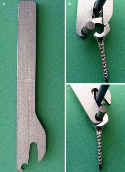
Fig. 13.4
(a, b) A screwdriver which is specially designed for the double-decker screw fixation.
Fig. 13.5
(a–c) A final rod insertion wrench which is designed for the easy insertion of the final rod while the provisional rod is in place
13.2.3 Brief Description the Use of the Rod link Reducer System in an Example of PVCR for an Angular Kyphosis
1.
With the spine exposed posteriorly, the pedicle screws will be inserted segmentally, except for the resected apical vertebra (Fig. 13.6).
Fig. 13.6
The double-decker pedicle screws are fixed, except for the apical vertebra
2.
The spine will be divided into cephalad and caudal portions by the resected vertebra. At the cephalad portion, two provisional rods will be fixed on the right and left sides via the top-loading component of the pedicle screw, respectively. Another two provisional rods will be similarly fixed at the caudal portion (Fig. 13.7).
Fig. 13.7
The provisional rods are fixed on the cephalad and caudal portion via the top-loading component of the screw. The rod link reducer connects the provisional rods and is locked via the universal joints to the shape of the deformity
3.
The two provisional rods on the right side will be connected with a rod link reducer. Another rod link reducer will similarly connect the two provisional rods on the left side. The rod link reducer will be locked via the universal joints to the shape of the deformity without any attempt at correction (Fig. 13.7). Resection of the vertebral column will be performed at the apical vertebra (Fig. 13.8).
Fig. 13.8
The resection of the vertebral column is performed at the apical vertebra
4.
A structural interbody support will be placed at the resected gap. The deformity correction will be performed by bilateral loosening of the adjustable universal joints of the rod link reducer, which will be gradually compressed to shorten the posterior elements of the resected gap (Figs. 13.9 and 13.10).
Fig. 13.9
A structural interbody support (cage) is placed at the resected gap. The deformity correction is performed by loosening the adjustable universal joints of the rod link reducer, which is gradually compressed to shorten the posterior elements of the resected gap
Fig. 13.10
After the deformity correction, the rod link reducer is locked again via the universal joints
5.
After the deformity correction, the rod link reducer will be locked again via the universal joints. Two final rods will be fixed on the right and left sides via the side-loading component of the pedicle screw respectively (Fig. 13.11). The two rod link reducers will be unlocked and all provisional rods will be removed (Fig. 13.12). A custom wrench will be used to remove the top-loading component of the pedicle screw (Figs. 13.13).
Fig. 13.11
The final rod (blue) is fixed via the side-loading component of the pedicle screw while the provisional rods and rod link reducer are in place
Fig. 13.12
The two rod link reducer is unlocked and all provisional rods (red) are removed
Fig. 13.13
The top-loading components of the pedicle screw are removed
13.3 Anterior Staple Tethering to Create an Angular Kyphosis in an Immature Pig Model
The animal surgery protocol was approved by the Institutional Animal Care and Use Committee. The 1-month-old pigs (5–8 kg) underwent general anesthesia with 6 mg/kg Telazol (Fort Dodge Animal Health, Fort Dodge, IA) administered intramuscularly. All received antibiotics preoperatively (35 mg/kg cephaxolin intravenously) and postoperatively (3 mg/kg ceftiofur intramuscularly twice a day for 3 days). The animals were placed in the left lateral decub itus position with the right side up. A curvilinear incision was made over the 15th rib (the most distal rib) for the anterior staple tethering from T14, T15 to L1. Following the incision of the muscle layers, a subperiosteal dissection was performed circumferentially around the rib. Medially a self-retaining retractor was near the costochondral junction. Following the incision of the costochondral junction and removing the 15th rib, the retroperitoneal fat was identified, which allowed gaining entrance into the retroperitoneal space. The abdominal contents were then bluntly dissected off the undersurface of the diaphragm and abdominal wall. The diaphragm, which was kept intact, ended on the body of the T14. The anterior edge of the psoas was sharply dissected off the spine and retracted posteriorly. The distal part of the vertebral body of T14, the disc of T14-15, the body of T15, the disc of T15-L1, and the body of L1 were exposed. The segmental vessels were then ligated individually with silk sutures. Thorough annulotomies and discectomies were performed at the two motion segments of the T14-T15 and the T15-L1. A Cobb elevator was used to sharply dissect the cartilaginous end plate off the bony end plate to allow complete removal as one segment without creating significant osseous end plate bleeding. A custom staple was placed over the level of the T14-15 and the level of the T15-L1 laterally, respectively. A longer custom staple was placed between the T14 and L1 more anteriorly (Fig. 13.14). The disc spaces of the T14-15 and T15-L1 were filled with the rib autograft. The rib was approximated by using a large #1 absorbable suture, and the periosteum of the resected rib was sutured. The abdominal muscle was closed in layers.
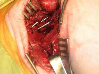
Fig. 13.14
Three custom staples are placed over the level of the T14, T15, and L1 to create thoracolumbar angular kyphosis in a 1-month-old pig model
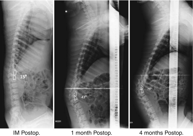
Analgesics (1.5 mg/kg flunixin meglumine) were administered intramuscularly twice a day for 3 days postoperatively. No postoperative immobilization was used. The animals were radiographed to assess the curve in the coronal and sagittal planes at immediate postoperatively and 1-month interval for 4 months. All animals survived without neurologic complications and remained normal and healthy for 4 months. An average 60° (51°–75°) angular kyphosis was created between the T14 and L1 in all 5 animals at 4-month follow-up (Fig. 13.15).