Shunt and Valve Technology
Scientific knowledge is based on independent research and observed evidence. The evidence for the superiority of a specific valve design has been of interest since the first shunt was implanted. Many publications have reported on the clinical experience with different types of valves; however, prospective randomized trials could not reveal significant differences.1,2,3 For the first time ever, significant differences were shown by Meier and co-workers4,5,6 who compared adjustable differential pressure (DP) valves with and without a gravitational unit. His results confirm the understanding that the hydrostatic pressure within a shunt system is the outstanding factor that must be taken into account and is systematically controlled by the characteristics of the valve.
9.1 Definition
A shunt is an artificial hydraulic connection between different compartments within the human body. In hydrocephalus, a shunt is used to connect a compartment filled with cerebrospinal fluid (CSF) and a cavity within the body where the drained fluid can be absorbed. In neurosurgical practice, the ventriculoperitoneal (VP) shunt is used most often. Usually a shunt includes a valve, which controls drainage throughout the shunt. Shunts without a valve are very rarely implanted.
9.2 Types
The history of the treatment of hydrocephalus reveals a wide variety of different approaches in draining CSF into a compartment within the human body where it can be resorbed. Most of these attempts have not been introduced in clinical practice and are only chosen today in cases when one of the already established shunt types fails for any reason. Nowadays the implantation of a VP shunt has become the standard practice.7 Other options are the ventriculoatrial (VA), the lumboperitoneal (LP), or the rarely implanted ventriculopleural shunt. The historical figure shows the compartments that have so far been chosen for drainage attempts.8
9.3 Physical Basics
The absolute atmospheric pressure depends on seasonal changes in the weather, and the altitude of the location. At sea level, the normal atmospheric pressure is defined as 10.24 m H2O (1,024 mbar). At high altitudes, the atmospheric pressure decreases with increasing height. If the pressure at sea level is 1,024 mbar, then the atmospheric pressure at a height of 5,000 m drops down to 540 mbar. Consequently, the importance of pressure depends on the location. This is true within a gas environment, and—even more importantly—within a fluid system.
However, the intracranial pressure (ICP) is defined as the difference between the absolute pressure within the ventricular system and the outer atmospheric pressure. Merritt and Fremont-Smith9 reported on ICP measurements in 1,033 healthy persons and found an average value of 13 cm H2O with a peak at 15 cm H2O (▶ Fig. 9.1).
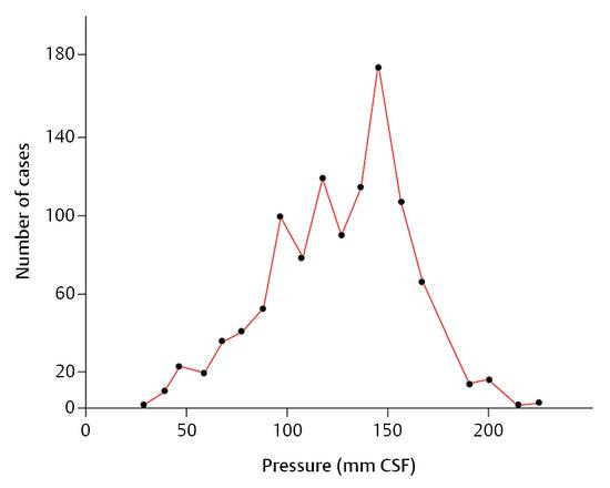
Fig. 9.1 Frequency-distribution curve for the intracranial pressure in 1,033 normal human participants.9
In a healthy person, ICP is determined by the production of CSF and its absorption. The production of CSF is independent of the pressure gradient between the ventricular system and the aterial blood vessels. However, the absorption depends on the gradient between the intraventricular and venous pressures. As the venous pressure increases, the ICP also increases.
9.4 Hydrostatic Pressure
Hydrostatic pressure is of utmost importance for the physics of CSF drainage and shunts. It is defined as
 (15)
(15)
where ph is the hydrostatic pressure (cm H2O), δ is the specific weight of the fluid (kg/L), g is the acceleration due to gravity (g = 9.80665 m/s2), and h is the height of the water column (WC; cm).
The hydrostatic pressure in a fluid increases with its depth. ▶ Fig. 9.2 demonstrates a simple experiment. The atmospheric pressure acts on the surface of the water. The absolute pressure under the surface increases with the depth. If a straw is put into a glass of water and the straw is closed by a finger and moved out of the fluid, then the water remains within the straw; now the surface of the water is below the column. The atmospheric pressure acts on the lower outlet of the straw, and the closing finger at the upper outlet is pulled into the straw due to the negative pressure within the straw. The higher the point where the pressure is measured within the straw, the lower the pressure. It is also clear that the hydrostatic pressure is higher as one measures deeper in the water reservoir. Within the straw, the pressure is the lowest at the top end of the straw, where the finger closes the straw. The finger is pulled into the straw because the pressure is lower than the surrounding atmospheric pressure.
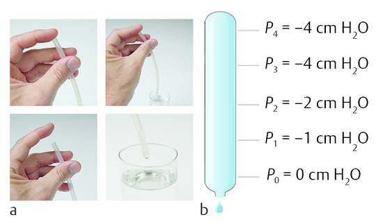
Fig. 9.2 Negative pressure within (a) straw and in (b) tube.
If the reference point is in the middle of the tube, then the pressure becomes negative going up and positive going down the tube (▶ Fig. 9.3).
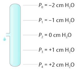
Fig. 9.3 Pressure changes within a tube with the reference level at one side.
Understanding hydrostatic pressure is also important for the peritoneal cavity. Within the peritoneal cavity exists a hydrostatic pressure that becomes positive going down and negative going up. The important question is: Where is the reference point, the zero level?
9.5 Physics of Ventriculoperitoneal Shunts
Every shunt has an inlet and an outlet. The outlet is connected to the absorption cavity (normally the abdomen or the right atrium of the heart), while the inlet is connected to the ventricular system of the brain. Two factors determine how much CSF will be drained through the shunt: the opening characteristic of the valve and the pressure situation at the outlet of the valve.
A container filled with water has an outlet at its bottom, where a tube is fixed with an integrated valve. The opening pressure of the valve defines the level of the water within the container, together with the pressure at the outlet of the distal tubing. If the distal tubing is lowered, then the water level within the container is lowered accordingly. In this model, the container can be seen as the ventricular system, and the opening at the outlet represents the pressure situation within the abdominal cavity. For this pressure not only is the value relevant (in this case, the atmospheric pressure), but the position is also important (▶ Fig. 9.4). This phenomenon is independent of whether or not the container is open or closed. If, for example, the container is covered with a thin membrane, then the membrane will sink if the distance between the outlet level of the tubing and the zero-level (an imaginary water level) is higher than the opening pressure of the valve and allows flow throughout the shunt (▶ Fig. 9.5). The drainage stops at the moment when the pressure is at the zero level.
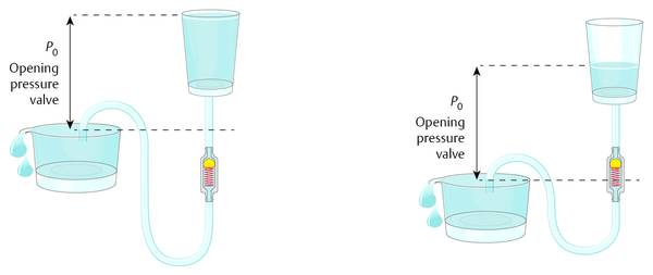
Fig. 9.4 Function of differential pressure valves.
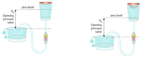
Fig. 9.5 Container with a shunt covered by a thin membrane.
The resulting pressure situation within the covered box is not affected by the characteristics of the membrane. If the membrane is stiff, like bone, then the drainage and the physics of the system can still be correctly described by this model (▶ Fig. 9.6). The pressure within the hard box (the ventricular system within the head) is determined by the outlet pressure and the level of the outlet together with the opening performance of the valve. Within the closed container there is obviously hydrostatic pressure that is becoming lower at a higher point within the hydraulic system and higher at a lower point.
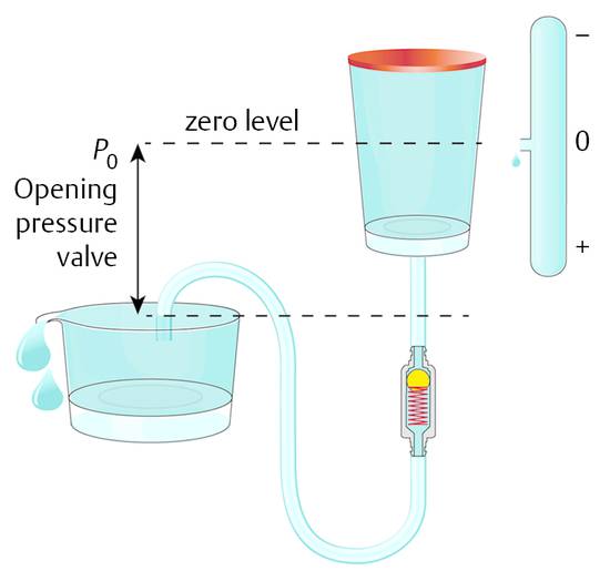
Fig. 9.6 Hard box model of the ventricles within the head with an integrated shunt.
Hence, the ICP of a shunted patient is first of all a result of the pressure in the volume into which the fluid is going to be drained. Currently, the abdomen is the preferred site.
If the pressure within the abdomen is so important for ICP, then how can this model be considered an open system? The fluid being drained into the abdominal cavity is normally not effecting the pressure situation within the abdomen; it is easily absorbed. Normally, the peritoneum is opened during surgery and the catheter is inserted without any control of the placement of the distal end. When the abdomen is opened, the fluid it contains can be seen between the organs of the abdomen. This fluid normally can freely communicate between the organs within the abdomen, and it establishes a hydrostatic pressure within the abdomen. For this reason, it is not important where the distal end of the peritoneal catheter is placed; however, the reference point (zero level) within the peritoneal cavity is important. It is obvious that the pressure within the peritoneal cavity depends on the activities of daily life of each individual patient. The nutritional condition, individual anatomic variations, movements, or features due to illness have a definitive impact on the pressure situation. However, on average, the widely accepted assumption is that, for a person in a horizontal position on his or her back, the zero level of the peritoneal pressure is at the point of the upper abdominal skin (a study by Freimann and Sprung) (▶ Fig. 9.7). This means that, for a patient who is obese, this point should be generally considered to be higher than for a patient who is thin. In terms of adequate shunting and avoidance of overdrainage, the horizontal position is logically less important than the upright position. Normally overdrainage in the upright position is more challanging. However, more seldomly underdrainage in the horizontal position in obese patients might be a problem as well.
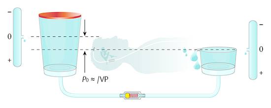
Fig. 9.7 Model of a differential pressure valve in a patient lying in a horizontal position.
When the patient is in the upright position, the physics within the abdomen changes because the direction of gravity is different. The abdomen is still a hydraulic compartment with hydrostatic pressure; however, the zero level in the upright patient moves toward the region of the diaphragm (▶ Fig. 9.8).
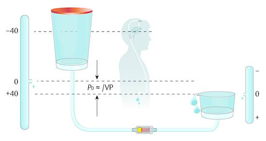
Fig. 9.8 Shunt physics of a differential pressure valve in a patient in the upright position.
For any position of the shunted patient, a “zero level” exists as a reference point for the function of the shunt. Essential for the flow throughout the shunt is how far, how often, and how long does this reference point (zero level) shift. The average rate of production of CSF is known to be about 20 mL/h. A shunt allows a flow that is several times higher than this rate of production.10 Therefore, in cases of temporarily increased intraperitoneal pressure, the shunt can easily compensate for underdrainage as soon the peritoneal pressure drops to normal values. For this reason, the risk of underdrainage is not very relevant as long as the pressure shift within the abdomen does not occur for periods longer than an hour or two. This is different for the opposite situation: if the abdominal pressure decreases temporarily for any reason, this automatically leads to decreased ICP, which is not as easily compensated as underdrainage because of the low rate of production of CSF compared to the high flow rate of a shunt.
The absorption capacity of the peritoneum is so high that the CSF, which is drained into the peritoneum, does not change pressure. The zero-level reference remains more or less at the same level regardless of the bulk flow of the CSF.
9.6 Ventriculoatrial Shunts
In contrast to VP shunts, the placement of an atrial catheter on the distal tip of a VA catheter is very important for the resulting ICP. The pressure within the vena cava, the right atrium, or the right heart varies significantly. Consequently, precise positioning of the tube is mandatory. In principle, the function of shunts as described above is also true for VA shunts. The posture-dependent changing values are different because the reference points are different. Therefore, the physics of VA shunts require a posture-dependent function as with VP shunts. Depending on individual anatomy, the hydrostatic difference from the foramen of Monro to the right atrium is lower than the distance to the diaphragm. Accordingly, the hydrostatic compensation in the upright patient is lower. Generally, the percentage of complications with VP and VA shunts seems to be comparable, although complications with VA shunts are more severe and more difficult to treat.11,12,13,14
9.7 Classification of Valves
All available valves can be classified into four subtypes. ▶ Table 9.1 gives an overview. The classification follows mechanical characteristics. Basically, there are only two groups, namely DP and hydrostatic valves. In principle, the option of a noninvasive readjustment does not change the hydraulic performance. The valve works following the adjustment, but it is still a DP or a hydrostatic valve. The adjustment simply avoids the otherwise necessary valve change. However, once adjusted it works like a nonadjustable valve during the daily life of the patient.
Valve | Fixed | Adjustable |
DP valves | ||
Silicon slit | X | |
Membrane | X | |
Ball-in-cone | X | X |
Hydrostatic valve principles | ||
ASD technology | X | |
Flow reducing | X | |
Gravitational | X | X |
Abbreviations: ASD, antisiphon device; DP, differential pressure. | ||
DP valves were the first valves to be used successfully in the treatment of hydrocephalus. Spitz, Holter, and Nulsen were the pioneers who introduced these valves in the early 1950s.15,16,17,18 This was a definitive breakthrough in the treatment of hydrocephalus and the beginning of modern shunt therapy. Since then, many different models have been proposed to improve the clinical outcome or the surgical treatment.
In patients receiving shunt therapy, ICP generally is controlled by the opening characteristic of the valve and—even more importantly—by the pressure within the peritoneal cavity. The valve simply transmits the referential pressure within the peritoneal cavity to the ventricles in the brain by adding the value of the opening pressure. A noted drawback of DP valves is the fact that they do not take into account the posture-dependent physics of shunts in patients with hydrocephalus. Although the first proposals to overcome problems due to overdrainage go back to the 1960s and 1970s,19 the importance of a consequent hydraulic compensation of the posture-dependent physics is still underestimated and is seen as a rare or not-too-important complication. Some clinical reviews report a very low incidence of overdrainage, especially in children.2,20 However, on the other hand, the list of overdrainage-related complications in children and in adults is long and well described in other papers.21,22
DP valves, neither fixed pressure valves nor adjustable devices, do not and cannot fulfill the requirements for both horizontal and upright position of patients. In the upright position, the reference point within the peritoneum, on average, is the diaphragm. At this point, the inner pressure is more or less equal to the atmospheric pressure. The implanted shunt, together with the ventricular system of the patient and the peritoneum, is a hydraulic system of connected compartments. Again, based on the pressure situation in the abdominal cavity, the DP valve transmits the reference point, or the zero-level.
A typical DP valve with an opening pressure of 10 cm H2O, for example, can shift this zero level 10 cm above the diaphragm. ICP within the ventricles at the foramen of Monro of normal healthy individuals without a shunt is about 0 cm H2O, which means that it is about equal to the atmospheric pressure at this point. Depending on the height of the individual patient, the DP valve will have to compensate the height difference from the diaphragm to the ventricles. In adult patients this typically is about 30 to 40 cm H2O; in children or newborns it is accordingly less. A DP valve with an opening pressure of only 10 cm H2O, which, for the horizontal position fulfills the requirement of a physiological ICP, keeps ICP at negative values in the upright position: –20 to –30 cm H2O in adults, and –10 to –20 cm H2O in children. These values are not physiological, neither in adults nor children. Whether or not this fact leads to complications such as subdural effusions, ventricular collapse, or headache seemingly depends on individual structures and their ability to withstand this suction. As ICP becomes more negative, there is a higher risk of hematoma, for example, as a consequence of a ruptured bridging vein. The fact that a subdural effusion does not always develop in all patients with a negative pressure in the upright position does not mean that the ICP is not significantly negative. Regardless of whether or not there is a clinical complication in all shunts with DP valves, the pressure in the upright position becomes negative. Therefore, a DP valve is an insufficient solution in principle, even though it solves the underlying problem of the pressure crisis due to hydrocephalus.
Despite these considerations, various types of DP valves have been developed and implanted with good clinical success. However, clinical studies have not confirmed one or other valve design as being superior.2 However, laboratory investigations have revealed significant mechanic and hydraulic differences.
The oldest design in the group of DP valves, the silicone-slit valve, shows a flow-reducing performance that is somewhat similar to the performance of the so-called flow-reducing devices.18,23,24 The membrane and ball-in-cone valves have a similar hydraulic performance, whereas the ball-in-cone valves demonstrate the most reliable function and precision.25,26 The silicone-slit valves get their characteristics from the stiffness of the silicone. The simplest model of a silicone-slit valve is a catheter with a closed end and one or several slits close to the end of the tube. The stiffer the material, the thicker the wall of the tube, and the smaller the slit (incision) in the tube, the fewer slits there are, the higher the opening pressure becomes. More sophisticated models show a cross-incision at the closed end of the tubing (▶ Fig. 9.9). Silicone-slit valves are rarely used today.
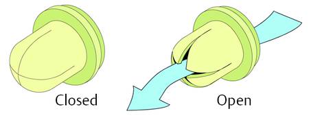
Fig. 9.9 Typical silicone-slit valve.
The second type of nonadjustable DP valve is the membrane valve. The opening performance of this device is defined by the stiffness of a membrane, which closes the pathway by sealing against a valve seat. The normally flat, rounded membrane is fixed at the valve housing in the way that the valve is closed; the membrane covers the valve seat. If the DP acting on the valve seat exceeds the opening pressure, then the flexible silicone membrane is displaced from the valve seat at the outer end and the valve opens. To achieve a different opening pressure for the different valve ranges, membranes of different thickness are used. The membrane gets thicker and becomes stiffer as the opening pressure rises (▶ Fig. 9.10).
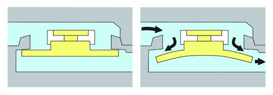
Fig. 9.10 Closed and open membrane valve.
Ball-in-cone valves represent the third group of DP valves available on today’s market. A round valve seat is closed by a metallic or sapphire ball, and it is kept in the seat by the force of a metallic spring (▶ Fig. 9.11).
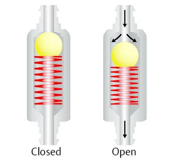
Fig. 9.11 Ball-in-cone valve.
The spring can be a classical cylindrical or a kind of leaf spring. The opening pressure of such a valve can be calculated by
 (16)
(16)
where p is the opening pressure of the device, F is the force of the spring, and A is the area closed by the ball at the valve seat.
Consequently, the spring force needed to establish a certain opening pressure depends on the diameter of the valve seat. For hydrocephalus valves, this aspect offers the opportunity to decrease the influence of sticking particles in the CSF on the valve function by choosing large areas with consequently strong forces27 (▶ Fig. 9.12).
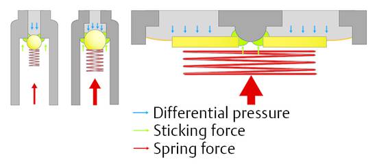
Fig. 9.12 Ball-in-cone valve with different springs and valve seats.
A combination of ball-in-cone and membrane valves introduces the option to increase the opening or operating forces in a way that the sticking forces, which influence the function of the valve, remain small in comparison with the operating force (▶ Fig. 9.12, right). This principle is established in the (hydrostatic) DUALSWITCH valve27,28 and the MONOSTEP valve. In these devices the ball-in-cone principle is inverted: the ball, which closes the valve at the valve seat, is not movable, but the seat is integrated into a movable membrane. The ball is part of the fixed housing. If the DP at the valve seat increases, then it overcomes the spring force at a certain point, which defines the opening characteristic of the valve, and the valve opens. If the area on which the pressure is acting is more than 200 times larger than in any ball-in-cone valve, then the force to overcome possible sticking effects is 200 times larger than in the other ball-in-cone valve. Clinical papers reporting the experience with these devices have confirmed their reliability.28,29,30,31,32,33,34,35,36,37
A different concept for lowering the likelihood of blockage is the underlying concept of the smallest available DP valve. The miniNAV has dimensions that are barely larger than the diameter of the catheter. The channels within the valve are smaller than the inner diameter of peritoneal tubes. At any place within the valve the flow is always higher than within the catheter; this might lower the risk of protein collection within the valve. However, there is no clinical evidence for the superiority of one DP valve design over the other, neither in terms of blockage nor in terms of function (▶ Fig. 9.13).
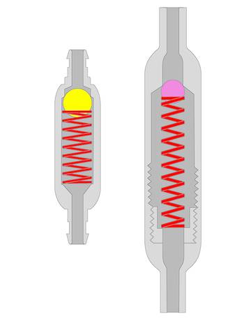
Fig. 9.13 The miniNAV concept in comparison with other differential pressure valves.
9.8 Adjustable Differential Pressure Valves
Adjustable DP valves represent the most popular and current type of valves. These valves allow the valve characteristic to be adapted to the clinical situation of the patient.38 Nonadjustable DP valves are available with different opening characteristics. The opening pressures vary from manufacturer to manufacturer. Valves are offered with very low, low, medium, high, and very high opening pressures. Very low is equal to 2 to 4 cm H2O and very high is equal to 18 to 20 cm H2O. Depending on the experience, the surgeon chooses an opening pressure that he or she believes to be the best option for the patient. This choice is not based on scientific clinical evidence, because it has not been shown that one opening pressure offers a clinical outcome better than the other. As a general rule, it seems logical and acceptable that a high resistance (opening pressure) decreases the risk of overdrainage and a low resistance decreases the risk of underdrainage. In patients with an unsatisfactory clinical outcome or complications, such as subdural effusion (overdrainage) or remaining clinical symptoms (underdrainage), the implanted DP valve is revised and changed to one with a lower or higher opening pressure. Alternatively, based on the growing evidence for hydrostatic components, a siphon-compensating device is also implanted (see Section ▶ 9.9).19,21,23,24,25,29,31,32,39,40,41
To avoid the additional revision, adjustable devices have been developed that allow noninvasive adjustment of the device. In cases of underdrainage, the opening pressure can be decreased; in cases of overdrainage, the valve pressure is increased (▶ Fig. 9.14).
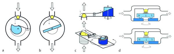
Fig. 9.14 Principles for pressure adjustments in hydrocephalus shunts. (a) proGAV principle. (b) Sophysa principle. (c) CODMAN MEDOS principle. (d) STRATA principle.
Adjustable devices are popular up to now although their superiority versus nonadjustable DP valves has not been confirmed.42,43,44 This might be surprising because the avoidance of a further revision should improve the survival of an implanted valve. One explanation might be the high influence of the infection rate on the survival curve, which is the same for both adjustable and nonadjustable devices. However, this aspect alone does not explain why the outcome of adjustable devices is not significantly better. This can be explained by the limited value of adjustable devices in accordance to their mechanical performance as a DP-valve. Adjustable devices do not solve the problem. They only shift it.
There are two reasons for adjusting the valve. The first reason is an unsatisfactory clinical outcome leading to suspicion of underdrainage. In this case, the opening pressure of the valve is decreased. The other reason is the adjustment of the valve to a higher value to treat overdrainage. However, both actions are, at the same time, biased because of systematic drawbacks produced by the change of the valve setting: increasing the opening pressure leads to underdrainage in a patient in a horizontal position, while decreasing the opening pressure increases the risk of overdrainage in an upright patient.
The available adjustable DP valves offer the option of a pressure setting between 0 and maximum 20 cm H2O. In cases of overdrainage, the valves are adjusted to 20 cm H2O. For an average adult patient, this value is too low. As the hydrostatic pressure within the silicone tube of a shunted patient can easily be 40 cm H2O, the adjustment up to 20 cm H2O cannot counterbalance this value. This means that, even with the highest adjustment, the goal of physiological pressure values cannot be achieved. ICP remains too negative at –20 cm H2O, so the subdural effusion cannot be treated. At the same setting, the pressure situation in the horizontal position becomes too high. The normal range of ICP is about 10 to 15 cm H2O. With an adjustment to 20 cm H2O, the ICP is too high, and the ICP grows to hydrocephalic values after longer periods in a horizontal position. This is especially critical for patients with normal pressure hydrocephalus (NPH), because it is known that a low-pressure setting is beneficial for a good clinical outcome.34,45 The advantage of a lower risk for severe overdrainage-related complications in the upright position is diminished by the drawback of underdrainage in the horizontal position (▶ Fig. 9.15).
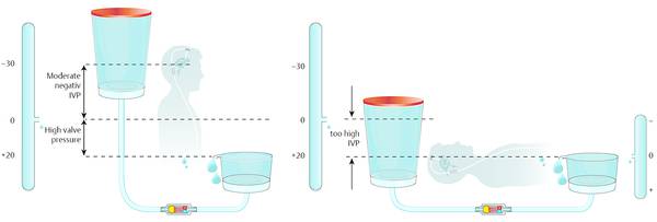
Fig. 9.15 High setting of an adjustable valve: there is still overdrainage in the upright position and underdrainage in the horizontal position.
The opposite can occur in patients with unsatisfactory clinical outcomes combined with suspected underdrainage. In these patients, adjustment of very low opening pressures dramatically increases the risk of overdrainage-related complications when the patient is in an upright position (▶ Fig. 9.16).
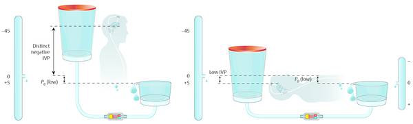
Fig. 9.16 Adjustment to a low valve setting in patients with suspected underdrainage.
There is no clinical evidence for the superiority of adjustable valves, but there is mechanical evidence that DP valves do not guarantee physiological pressure establishment in patients with NPH. However, this type of valve is far more expensive than nonadjustable devices, but they are well accepted and commonly used.41
The first adjustable valve, which was introduced into the market in the late 1980s, was the so-called Sophysa SU8. This valve offers eight pressure settings between 4 and 20 cm H2O. The cylindrical flat housing incorporates a rotor with two magnets, one at each end, and it is fixed on an axle in the middle of the housing. At one end of the rotor, an arc-shaped leaf spring is fixed on the rotor in such a way that, if the rotor is turning, then the spring changes the relevant length of its lever. Thus, the active length of the spring changes, defining the resulting opening pressure of the device. The pressure becomes higher if the active length of the spring is short. The setting of the valve is the lowest if the active length of the spring is the longest. The long spring exerts a low force on the ball at the valve seat and the short spring exerts a high force and consequently a high opening pressure of the valve. To decrease the risk of unintended readjustments, the nonrelevant part of the spring is snapped elastically into a groove in the outer housing (▶ Fig. 9.17).
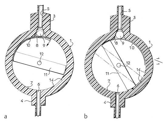
Fig. 9.17 (a and b) The first adjustable differential pressure valve on the market, the Sophysa SU 8.
The adjustment of this device is performed by magnets from the outside, which have to be placed in such a way that the rotor within the housing moves into the required position for the required opening pressure. The most important drawback of this device is the fact that it can be easily readjusted by magnets routinely used in daily life.46 The setting of the highest and lowest value is established by turning the rotor in a range of about 90°. The position of the rotor can be determined from outside with the help of a compass. The needle of the compass follows the position of the magnets inside the rotor. With the right orientation in parallel to the inlet connector of the implanted device, the position of the needle allows the reading of the pressure setting. Due to the fact that the rotor can be turned in an angle of about 90° only, there is a certain risk of a misreading. In cases of problems, the adjustment can be controlled with radiography.47
To improve this device and avoid the risk of an unintended readjustment of the valve while it was implanted, the company Sophysa48 developed the Polaris valve. This device introduced the radial movement of the magnets within the rotor. Due to their orientation the magnets are normally pulled toward the axle of the valve. In this position the rotor cannot be turned around because the movable parts snap into notches, which hinders the rotor turning around. To perform an adjustment, magnets from outside, which are stronger than the magnets within the valve, force the valve magnets to move toward the outer housing away from the axle in the middle of the housing. In this position the rotor can move freely, and adjustment is easily possible (▶ Fig. 9.18).49
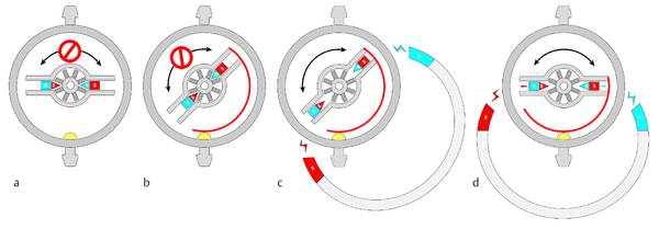
Fig. 9.18 Principle of the Polaris valve from Sophysa. (a) Rotor locked, no adjustment possible. (b) Rotor unlocked by external magnets, adjustment possible. (c) Position of the unlocked rotor is changed, rotor still unlocked. (d) Rotor locked in the new position after the readjustment.49 Printed with permission.
The second adjustable valve brought into the market was the CODMAN HAKIM valve, which is called the MEDOS CODMAN programmable valve by the manufacturer. A leaf spring exerts force on a ball into a valve seat, whereby the force of the spring can be adjusted by controlled magnetic fields placed above the device from outside. On one side, the spring lies on the ball at the valve seat; on the other side the spring lies on the “stairs” of a rotor, which can be turned through 360°. While turning, the spring climbs (or goes down) the stairs and this changes the opening pressure. To perform an adjustment, the company Codman 50 offers a special tool, which creates the magnetic fields above the device. The rotor incorporates eight small magnets, which are cylindrically placed at the outer end of the rotor. The north-to-south orientation of the magnets is in parallel to the rotor axis and changes from neighbor to neighbor. The rotation of the rotor during the adjustment process happens in steps of 20°. The adjustment apparatus placed above the valve first creates magnetic fields with a changing orientation in a way that the valve is adjusted stepwise to the lowest setting. This means that the spring lies on the lowest stair of the rotor in this position, as the spring cannot jump to the highest stair next to the lowest. From this point, the apparatus starts turning the rotor in the opposite direction in steps of 20°. One step is equivalent to a pressure change of 1 cm H2O. The highest adjustment is 20 cm H2O; the lowest is 3 cm H2O. Once the setting is achieved, it cannot be controlled without radiography. This is a very important disadvantage of this device (▶ Fig. 9.19).51
A second important problem of the MEDOS HAKIM valve is the fact that it can be readjusted accidentally whenever an external magnetic field acts on it. There are several reports in the literature that confirm the relevance of this drawback.52,53,54,55,56 Serious complications are reported especially in patients in whom the valves are unintentionally readjusted from the highest to the lowest value. If the valve is adjusted to the highest setting (20 cm H2O) and the rotor gets turned by 20° in the appropriate direction, the setting switches down to 3 cm H2O, which is the lowest setting. This is especially dangerous because the intended adjustment was an increase in opening pressure to the highest possible value.53
The requirement that the adjustment must be confirmed by radiography is especially important for the pediatric population wherein X-rays generally should be avoided. For this reason, the manufacturer introduced a device that acoustically controls the correct setting of the valve. A microphone detects each single sound induced by the spring, as it climbs from one step to the next during the adjustment procedure. If the device is not able to detect as many typical sounds as pressure steps that have to be adjusted, the procedure must be repeated or the information is given that the adjustment was not successful. Independent investigations of this device confirmed the function in general; however, the function could not be guaranteed in 100% of patients. Therefore, the device requires radiographical confirmation of the adjustment, not just from a legal standpoint.57,58
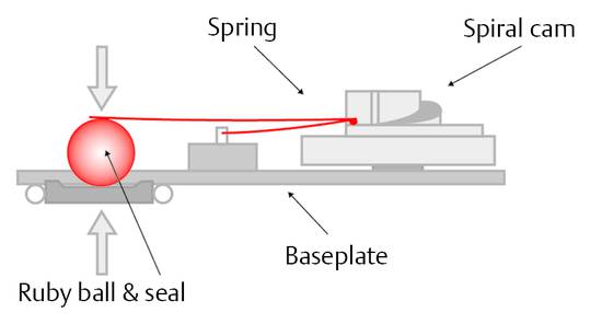
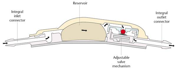
In the 1990s, PS-Medical (Medtronic) introduced another adjustable DP valve, the so-called STRATA valve. This valve is also readjusted by external magnets placed above the implant. The valve mechanism incorporates two different springs: one determines the opening pressure; the other keeps the rotor in the appropriate position as long as there is no magnetic field around it, which pulls the rotor up against the weaker spring force. In this position, the rotor can be rotated following the rotation of the outer magnet. The turning rotor changes the spring force of the device that determines the opening pressure. The valve is available with five different settings from 2 to 15 cm H2O (▶ Fig. 9.20).59,60
Related posts:


Stay updated, free articles. Join our Telegram channel

Full access? Get Clinical Tree


