Fig. 21.1
Square pulse commonly used for spinal cord stimulation which is dependent on amplitude and pulse width
The pulse or stimulation rate can be manipulated to create distinct pulses. Settings of the SCS can vary between a low rate or a merging of pulse sensations with higher frequency stimulation. Lower frequencies result in a more distinct, slower pulse, while higher frequencies result in a more continuous, smoother sensation.
Complex mathematical modeling of the impact of these parameters on SCS function has been done. Named for Jan Holsheimer, the concept of mapping out the proper lead positioning and concomitant SCS parameters for optimal effect has become known as Holsheimer mapping [8]. While they are advanced concepts, the mathematical underpinnings of SCS programming are important issues to understand when complex programming is required. Pulse width provides an illustrative example of this concept. For example, if a spinal cord stimulator lead is placed in a more lateral position within the epidural space, a longer pulse width may activate the spinal cord nerve root and cause discomfort. In this scenario narrowing the pulse width may be beneficial.
Electrical Field
The shape of the electrical field created is dependent on the configuration of anodes and cathodes. In a simple system using one anode and cathode, charge flows as described above with very little ability to “shape” the contour of the electrical field (Fig. 21.2). Over the last 10 years the utilization of an electrode combination referred to as a “guarded cathode” has proven useful. This configuration has anodes on either side of the negative cathode setting up an electrical barrier to the spread of the electrical field, driving the field in a targeted fashion (Fig. 21.3). This concept is important to successful trialing of SCS as the ability to “steer” current toward the target areas of pain determines the ability to produce the overlapping paresthesia. In the above example the clinical usefulness of driving charge deeper into the spinal cord may be the difference between successfully capturing the desired paresthesia level and an unsuccessful trial.
Fig. 21.2
Single anode and cathode configuration
Fig. 21.3
Guarded cathode configuration
Technical Aspects of Lead Placement
Pre-placement Planning
Spinal cord stimulation can be utilized at all spinal levels and as such requires some pre-placement planning. For example, cervical leads can be placed at the cervico-thoracic junction or via a lumbar access site with the lead maneuvered through the epidural space to the cervical target. Both approaches have merit, but different applications. If one is conducting a temporary trial, then the “work” of threading leading leads from the lumbar spine for a patient who may not derive benefit may be futile [9]. Conversely, if the leads are for a permanent implant, the lumbar placement negates the need for lead extensions or extensive subcutaneous tunneling. Similarly if leads are to be placed in the sacral space, a decision must be made whether to attempt placement in a retrograde fashion or via the sacral hiatus.
While there is wide variability among individual patients, there are some guidelines with regard to lead placement targets which may assist the clinician in pre-placement planning. For instance, it is widely accepted that in the cervical spine the C2–C5 region will encompass the shoulder to the arm/hand. Likewise many have observed that obtaining paresthesia coverage for pain in the cervical axial spine is often difficult. Pain of thoracic origin can be broadly categorized as intercostal and visceral. Intercostal paresthesia can often be obtained at or just above the thoracic level of injury in a lateral position, while visceral pain (an area of emerging application for SCS) is currently not well defined and can be highly variable when obtained at all. Paresthesia coverage of pain of lumbar origin is better described. Classic teaching states that the “target zone” for most lumbar pain has an upper limit at T8 level with neurologic mapping undertaken to find the exact location between T8–L1 that works best for a given patient. Lumbar lead placement between L2 (termination of the spinal cord) and L5 is occasionally helpful and has many features in common with nerve root stimulation since the dorsal horn terminates at the T12–L1 level with the conus medullaris (the distal portion of the spinal cord proper at the L1–2 level). Sacral targets, though technically difficult to access, typical are relatively straightforward in their pre-placement assessment in that the effected painful level is typically the optimal site for lead placement.
Physiologic vs. Anatomic Positioning
Regarding “ideal” lead placement, there is considerable variability among individual patients. Many times “ideal” lead placement based on the fluoroscopic images obtained during initial placement (Fig. 21.4) results in nontherapeutic paresthesia patterns, the second image (Fig. 21.4) being the physiologically correct placement for that particular patient. This observation has led to the description of an anatomical midline and a physiological midline or “sweet spot” (Fig. 21.5). This jargon is describing the consistent finding that ideal anatomic position of the SCS lead under imaging (anatomic midline) often requires repositioning of the lead to less aesthetically pleasing, but more desirable physiologic position to obtain paresthesia coverage of the painful area (physiologic midline). This concept suggests that dorsal column fiber position is variable among individuals, even when the spinal cord is clearly midline on MRI or CT scanning. Another aspect of this physiologic mapping that must be considered is the common observation that one patient may report paresthesia into their feet at T8 while others will experience this same sensation at T10. Further, some individuals, despite meticulous repositioning, never achieve desired paresthesia coverage of the painful area.
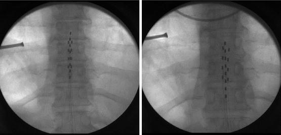
Fig. 21.4
Fluoroscopic image obtained during initial placement (left panel) of the “ideal” lead placement and the physiologically correct placement for this particular patient (right panel)
Fig. 21.5
The anatomical midline and the physiological midline or “sweet spot,” terms that describe the consistent finding that ideal anatomic position of the SCS lead under imaging (anatomic midline) often requires repositioning of the lead to less aesthetically pleasing but more desirable physiologic position to obtain paresthesia coverage of the painful area (physiologic midline)
Anatomical Conservations
Fiber location within the spinal cord, while also variable, does have some general principles that warrant discussion. Nerve fibers of more distal structures are contained in more central locations within the spinal cord. These fibers become more superficial as they near the exit point within the spinal cord. A spinal cord homunculus analogous to the homunculus at motor cortex has been described that suggests that sacral, lumbar, and thoracic fibers occupy fixed positions within the spinal cord ranging from medial to lateral, respectively (Fig. 21.6). While this concept is widely taught, paresthesia mapping during trialing suggests that the concept of fiber position is of little practical value as the important lead position is the one that has practical clinical value to the patient. Also, it has been reported that nociceptors that innervate the axial spine are located at deeper levels within the spinal cord and as such require complex combinations of pulse width and amplitude to achieve penetration to these fibers [10].
Fig. 21.6
Nerve fibers of more distal structures are contained in more central locations within the spinal cord. These fibers become more superficial as they near the exit point within the spinal cord. A spinal cord homunculus analogous to the homunculus at motor cortex has been described that suggests that sacral, lumbar, and thoracic fibers occupy fixed positions within the spinal cord ranging from medial to lateral, respectively
Distance between the dura and the spinal cord significantly impacts SCS. The dural cerebrospinal fluid volume varies widely along the length of the spinal cord (Fig. 21.7) and influences the dispersion of current. The CSF levels are maximal at the T5–7 level, which fortunately from a clinical standpoint decrease in the common target zones of C4–6 and T8–L1. The CSF volume at T8–L1 is still significant enough to impact stimulation.
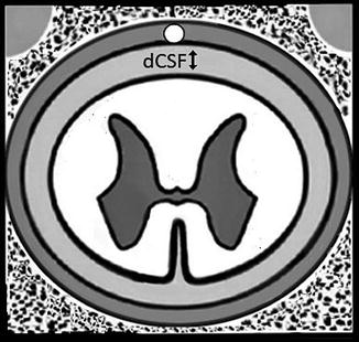
Fig. 21.7
The dCSF thickness varies along the spinal column and can significantly impact stimulation
Technical Considerations and Trialing Techniques
Technical Considerations
The number of contacts and leads to be utilized in SCS treatment is a matter of much conjecture and little conclusive evidence. In the mid-2000s, a single or dual 4-contact lead system was the state of the art. A study conducted during this period suggested that there was little advantage in adding a second lead for either radicular lower extremity and/or low back pain [11]. In this study the dual lead system was associated with faster implantable pulse generator (IPG) discharge, without significant improvement in perceived pain relief. Technological advances in IPG battery life coupled with more sophisticated programming options have led to rapid adoption of eight-contact leads which when used in an 8 × 2 array result in all channels of the IPG occupied and available to be utilized [12]. A 16-contact lead has recently entered the market and is already undergoing clinical testing using a 16 × 2 array for enhanced coverage and reducing the need for lead adjustment due to lead migration. The enhanced coverage would only necessitate reprogramming as opposed to additional surgeries.
Leads configured in multiple combinations such as two leads (bipole) and three leads (tripole) have been suggested to enhance coverage of low back pain. This concept is currently under investigation. The introduction of the tripole concept allows the clinician to mimic lead contact coverage obtained with a surgical plate or “paddle” lead [13]. The broad “paddle” lead has wider contact spacing allowing coverage of a wider area within the spinal cord. There also seems to be less lead migration with the paddle lead.
Another advantage over the percutaneous lead lies in the shape of the lead itself. The cylindrical percutaneous lead “radiates” an electrical field in a 360° direction while the surgical paddle lead directs current toward the spinal cord. It has been proposed that this arrangement directs current “deeper” into the spinal cord and may allow better axial back pain coverage. With the multiple contact percutaneous lead the greater contact capability (8 × 1) does allow the clinician to potentially retain paresthesia coverage even if small degrees of lead migration occur [14]. It remains to be seen if the increased number of contact points is of significant benefit from a clinical perspective.
Interleaving
The programming capabilities of multiple contact points allow the programmer to utilize an advanced concept known as interleaving to cover multiple areas of pain. The fundamental basis of this approach utilizes the programming of the IPG to rapidly (in microseconds) switch back and forth between programs on separate portions of the lead that cover different areas of pain. For example in an 8 × 2 configuration, lead contact 0–4 on a left-sided lead may cover low back pain while 11–15 on the right may cover the radicular lower extremity pain. With rapid cycling between the two areas of lead contact, the patient perceives coverage of both areas. The interested reader is directed to several excellent manuscripts on this topic.
Constant Voltage vs. Constant Current
As discussed previously, all SCS systems are bound by Ohm’s law in the way that they transduce the electrical signal to the biological system. If resistance (impedance in these alternating current systems) is relatively constant, and this is dependent upon the biological milieu, the only variables that can be manipulated are voltage or current. The advantages of both approaches can be theoretically debated with excellent arguments emerging for both types of systems. One study has compared constant voltage and constant current in a randomized trial, allowing the patient to determine whether there was a preference between constant voltage and constant current systems. In this small preliminary study, patients could not reproducibly identify constant current systems from constant voltage systems, suggesting that the theoretical differences may not translate into clinically meaningful differences in therapy [15]. This fascinating topic deserves further research.
Spinal Cord Stimulation Trial Techniques
After careful pre-placement planning has been accomplished, it is necessary to plan the trailing process. It is recommended that all patient candidates for SCS should undergo a pretrial psychological assessment to determine if there are unrealistic expectations, secondary gain issues, psychological issues that have not been maximally explored and treated, or other bio-psycho-social factors that may impact treatment success. Once this has been done, it is necessary to discuss with the patient the trialing technique. The purpose of the trial is to temporarily allow the patient to experience the sensation of SCS without having to endure the full implantation process with the IPG. There are two types of percutaneous spinal cord stimulator trials: (1) temporary percutaneous and (2) staged percutaneous placement with permanent anchoring of the leads. Each trialing method has advantages and disadvantages. The more common temporary percutaneous method entails securing the trialed lead to the skin with suture or other easily reversible material in a fashion that is quickly and simply removed. The percutaneous placement with permanent anchoring method requires surgical incision after lead placement and anchoring identical to that which is done with permanent implantation. The anchored leads are then connected to disposable trial connectors and exteriorized via tunneling in an operative setting.
The advantages of the more common temporary percutaneous placement in comparison to permanent anchoring method are (1) easy of placement and removal, (2) can be done in office procedure setting (whereas the surgical anchoring requires a traditional operating suite), (3) less post-procedure discomfort to distract the patient from the trial process, and (4) less invasive. Conversely the percutaneous placement with permanent anchoring results in a more accurate trial to implant experience and less surgical time required for implantation of the IPG [16]. Additionally the IPG placement can be performed under deeper sedation/general anesthesia since sensory mapping is not necessary. Occasionally, the results of the temporary trial are superior to the actual implant using the former method resulting in significant patient dissatisfaction. In the pretrial planning process if it is suspected that spinal epidural access or lead manipulation will be difficult it may be reasonable to do the staged trial with permanent anchoring; otherwise most centers utilized the temporary percutaneous method.
Regardless of trialing method, it is imperative that adequate time with the therapy be given to the patient to determine efficacy. Balancing the need for time with the therapy with the risk of infection usually results in 3–5 day trial period although some clinicians advocate for at least 7 days [17]. Experience with infection rates of epidural catheters suggests that any trial up to 7–10 represents low risk from an infection standpoint. During the trial, evaluation of functional capacity, sleep hygiene, and pain reduction is key. The person who does not derive functional benefit but claims pain relief should be evaluated closely.
Clinical Indications
While SCS has been utilized for a variety of painful axial and neurological conditions the main indications for the therapy are as follows:
Common Indications:
1.
Failed back surgery syndrome: It has been shown that SCS has better outcomes than reoperation. These findings suggest that a trial of SCS before considering a second back surgery should be a part of the treatment algorithm.
2.
Radicular pain: Pain of radicular nature in a classic dermatomal distribution in either the cervical, thoracic, or lumbar spine has a relatively strong evidence base suggesting efficacy.
3.
Neuropathic pain: Perhaps the strongest indication is the intense pain of neuropathic origin. Entities such as complex regional pain syndrome types 1 and 2, post-herpetic neuralgia, and post-amputation limb pain all respond well to SCS. Of these indications CRPS has strong clinical data to suggest efficacy.
4.
Peripheral vascular disease: Such as Raynaud’s phenomena, nonoperative limb ischemia, chronic angina, and Berger’s Disease.
While these clinical scenarios are well established as responding to SCS there are several exciting areas of emerging application for spinal cord stimulation. Many of these applications have evidence from the case report level to suggest they may improve pain control in patient who has exhausted other possibilities.


These off label applications include:
Related posts:


Stay updated, free articles. Join our Telegram channel
Full access? Get Clinical Tree
