Introduction
The established view of the pre-eminence of
MRI in spinal imaging is now being challenged by the growing appreciation of the value of MDCT. This is obvious in the assessment of spinal trauma but experience is showing its value in many acute and subacute spinal presentations. Because
MDCT can examine large spinal volumes rapidly, it is of great value in the assessment of possible spinal cord compression. Experience has shown that benign, malignant, and infective compression can be shown well with
MDCT. This is important because many patients with spinal compression have their imaging delayed waiting for
MR, and then up to 20% are excluded on safety grounds or find
MR impossible to tolerate because of pain and the need to lie supine for a long time.
MDCT can examine patients in any position they find acceptable in a matter of seconds. Accurate surgical localization is possible and the bone detail provides definitive information on spinal stability.
Degenerative disease of the cervical spine is simplest if examined with
MR but
MDCT will show soft disc and osteophytes well and any associated root compression. Primary or relapsed postoperative lumbar disc disease is also well shown in a
CT examination tolerated despite severe pain or obesity.
MDCT is often very useful in the acute situation when pain and lumbar spasm necessitates a quick accurate examination.
The entire lumbar spine can be imaged to exclude or confirm a clinical diagnosis of spinal claudication, giving excellent bone, disc, and ligamentous definition where
MPR can straighten out any rotational scoliosis common in the elderly degenerate spine. The standard three planes of
MR greatly limit this full assessment. Mass lesions at the craniocervical junction are optimally examined with
MDCT as has been illustrated in
Chapter 12.
In acute trauma, multiple noncontiguous fractures are common so it is essential to include all suspected levels of injury, or a complete spinal region, with a thin section helix to provide a complete assessment.
MDCTA is easily incorporated with the bone assessment if vessel injury is likely or suspected (see
Chapter 8). Low-dose techniques can be effective in the cervical region.
For suspected spinal compression the basic technique is for very thin slice acquisition following rapidly after 100 ml of
IV contrast given by hand or at 2 ml/sec. This increases the definition of the spinal cord, enhances the venous plexus to contrast with disc prolapse or osteophyte compression, and enhances infective/inflammatory/tumour tissue, differentiating it from the neural structures.
Spinal dural fistula and other vascular lesions can be accurately defined by
MDCTA which is now able to replace diagnostic spinal angiography if surgical treatment is planned for a fistula, or guide and shorten a diagnostic or therapeutic spinal catheter angiogram.
For ease of understanding, the variety of different
CT techniques applied to the spine, which are determined by the clinical site and possible pathology present, will be considered first. The pathologically based illustrations will follow to include all spinal areas.
Technique
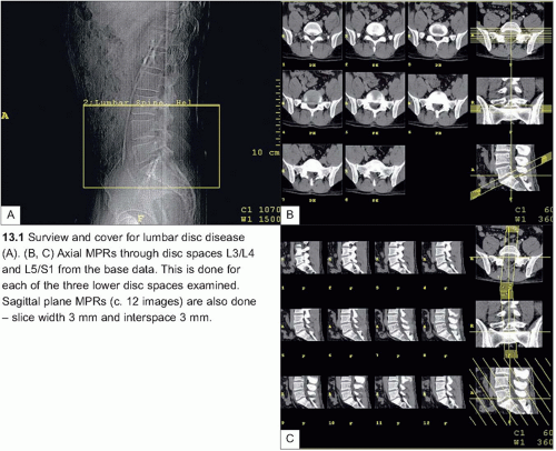
CT for lumbar disc disease
Table 13.1 presents optimal patient preparation, and the protocol is presented in
Table 13.2. A surview is shown in
13.1.
Multiplanar reformations
The dataset is used to create 8 axial multiplanar reformats parallel to each disc space using a slice width of 2.5 mm and a slice interspace of 2.5 mm; if the patient is very large a thicker slice (3-5 mm) will improve image quality.
Cervical/thoracic disc
For cervical or thoracic disc assessment the technique for spinal cord compression (see later) is best, but limited to the area of clinical interest. The contrast given enhances the epidural veins to aid the identification of small lesions.
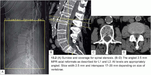
Spinal stenosis
When clinical history is suggestive of spinal stenosis (neurogenic claudication), the same parameters can be used to scan a larger area from the top border of L1 to the lower border of S1 (
13.2). A series of MPRs parallel to the discs is made, with one axial slice at the level of the pedicles and one through the disc of each level from L1 to S1 as illustrated (
13.2A, B). Additional reconstructions can be made if an additional disc prolapse or other bone pathology is found.
Extended spinal area examinations
Table 13.3 presents optimal patient preparation and
Table 13.4 presents the parameters for
CT spine. The parameters and techniques for
CT scanning of the spinal column are broadly similar, the only differences being in the use of suitable filters, contrast administration, and timing.
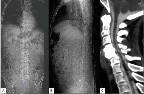
AP and lateral surviews for planning a thoracolumbar study are shown in
13.3. It should be extended if the cervical spine is to be included and/or reduced if only upper motor neurone features are present. If possible, dual projections are useful for spinal planning to ensure correct levels. For complete thoracic cover start the scan at C6.
In many situations the whole spine should be examined from the foramen magnum to the coccyx. If there is any doubt about the level of the possible pathology it is better for the scan to be inclusive and not exclusive.
CT for spinal trauma
The minimum cover is one vertebral level above to one level below the fractured vertebrae; however, multiple level fractures are common and the extent of injury not always clear on in initial clinical assessment and, increasingly, with the efficiency of
MDCT, complete spinal areas are examined.
Resolution: high
mAs: 150
Filter: bone
CT for cord compression
Plan the scan appropriate to the clinical findings and put the scanner to the start position. Give
IV contrast: 100 ml by rapid hand injection, or 100 ml at 2 ml/sec by high-pressure pump and scanning immediately after the end of injection.
Remember the site of any compressive lesion will be at or above the clinical level, never below it, and so as a general rule scan the whole spine or at least six spinal segments higher than the presumed site of pathology.
Resolution: standard
Filter: soft tissue in first acquisition with post-reconstruction with bone filter