Chapter 137 Spinal Implant Attributes
Distraction, Compression, and Three-Point Bending
Instrumentation techniques exert forces to the spine through six basic mechanisms: distraction, three-point bending, tension band fixation, fixed moment arm cantilever beam fixation, non–fixed moment arm cantilever beam fixation, and applied moment arm cantilever beam fixation.1,2 All of these mechanisms can be used individually or in combination. This chapter discusses in detail how various types of distraction, compression, and three-point bending implants carry these forces and redistribute them to the remainder of the spine and related tissues. Strategies are presented that can help prevent overloading any portion of the spine-implant combination (construct) and subsequent failure. The information presented in this chapter is an overview; more in-depth information may be gleaned from numerous sources.3–10 Implant-specific information is also available.11–14
Distraction Fixation
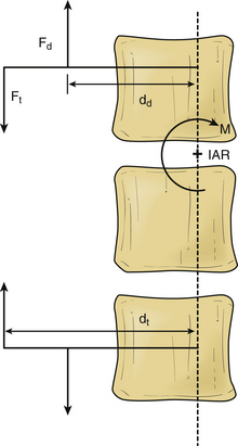
The use of distraction can be very effective in reestablishing spinal height. It can be applied from either a ventral interbody or a dorsal approach. However, it is uncommon to use distraction alone because it is difficult to apply forces directly in line of the instantaneous axis of rotation (IAR) or symmetrically around it. When distraction is applied away from the IAR, the resultant force develops a bending moment, as shown in Figure 137-1.
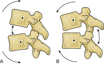
If we know the magnitude, the point and line of application of the distraction force, and the location of the IAR, we may predict the response of the spine segment.15 In these cases, the bending moment results in compression of the spine on the opposite side of the IAR from the site of distraction force application (Fig. 137-2).
The ability to resist bending (originated by the distraction) is called moment of inertia15; this is usually derived from intrinsic spinal elements (e.g., ligaments). The moment of inertia can be increased by tensile structures (ligamentous or implant) that are farther from the IAR than the distraction forces. The bending moment can be eliminated by balancing the distraction and tensile forces as shown in the following equation:
where Fd and dd are the distraction force and lever arm length, and Ft and dt are the tensile force and moment arm length (see Fig. 137-1).
The development of bending moments is particularly problematic when the isolated distraction forces are applied dorsal to the IAR. This difficulty is due to the propensity to exaggerate pathologically or cause a kyphotic deformity. Simple dorsal distraction is uncommonly applied, although it can be combined with three-point bending fixation to impart desirable results.
Three-Point Bending Fixation
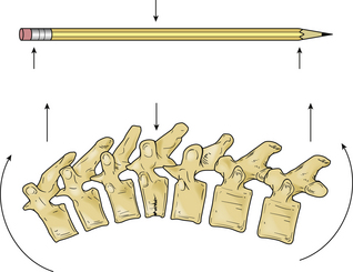
A pencil can be placed in three-point bending by placing the thumbs together in the center and the fingers at the ends and pushing on the center of the pencil with the thumbs. The resulting fulcrum directs a force vector opposite the direction of the terminal force vectors.1 The central force vector has twice the magnitude of the sum of the terminal force vectors and the opposite sign (Fig. 137-3).16 Three-point bending spinal instrumentation applies similar force vectors. They are usually, but not always, applied with an accompanying distraction force by using instrumentation such as Harrington distraction rods or universal spinal instrumentation.
The bending moment generated by a three-point bending fixation construct is proportional to the length of the construct.17 Three-point bending implants usually involve application of dorsal instrumentation over multiple spinal segments (five or more spinal segments). The forces at the rostral and caudal implant-bone interfaces are usually dorsally directed. The central force is usually in the ventral direction. This central force is equal to the sum of the two dorsally directed forces and is normally located over the dorsal surface of the vertebra that requires decompression (see Fig. 137-3). If the dorsal surface of this central vertebra is damaged so that it would not resist the application of the force, the location of ventral force application can be moved to the vertebrae above and below the damaged vertebra. The result is four-point bending fixation. The effects are very similar to three-point bending fixation, but larger forces or longer moment arms (more spinal segments) are required to obtain the same bending moment and decompression. Using the previous example with a pencil, this concept can be visualized by moving the thumbs apart while keeping the fingers in the same location when bending the pencil.
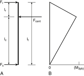
The forces and lengths are as defined in Figure 137-4A, and the system is assumed to be at rest. The requirement that the sum of the three forces be zero can be used to derive the moment in terms of the central force,11 as follows:
Figure 137-4B shows that the moment decreases linearly from the central loading point until it reaches a value of zero at the terminal loading points.
As discussed earlier, it is rare to apply isolated dorsal distraction forces; this is because dorsal distraction also results in flexion of the spine, as the IAR is ventral to the force application points. Because three-point bending fixation opposes this flexion, it is common to combine the two modes of force application. The application of sufficient dorsal distraction is needed so that the implant makes contact with the spine at the intermediate point along the construct (fulcrum), which is usually at the level of the pathology site; this can be accomplished by bending the rod so that it makes contact with the spine at the location at which the ventral force application is desired or by using a sleeve to increase the diameter of the rod at this location.14 Nevertheless, this technique has major disadvantages: (1) Achieving proper rod modeling is highly difficult; (2) multiple bends fatigue the rod and may result in failure; and (3) round rods can rotate at the hook interface so that the bend is no longer in the sagittal plane.
Terminal Three-Point Bending Fixation
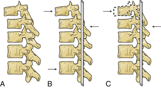
The term terminal three-point bending fixation is used to define a three-point bending construct that corrects sagittal deformation situated at the rostral end of an implant. In this case, the fulcrum is situated near one end of the construct.1 The moment arm attained by a terminal construct is less than the moment arm attained for a similar three-point bending construct where the fulcrum is in the midportion.
This type of construct may be useful in the clinical scenario of a sagittal deformation where the rostral segment is translated in a ventral direction with respect to the more caudal segment.1,17 In this case, the use of a terminal three-point bending fixation construct results in reduction of translational deformation. It eliminates the pressure on the spinal cord by the dorsal surface of the spinal canal. Application of the ventral force by using the rostral terminus is much easier because the vertebra to be moved can be affixed to the rod, while the remainder of the rod is used as a lever (Fig. 137-5). In this application, the length of the rostral portion (lr) is normally quite short (one segment), and the length of the caudal portion (lc) is longer (two to four segments), which allows a large rostral force with application of a small caudal force.
Stay updated, free articles. Join our Telegram channel

Full access? Get Clinical Tree


