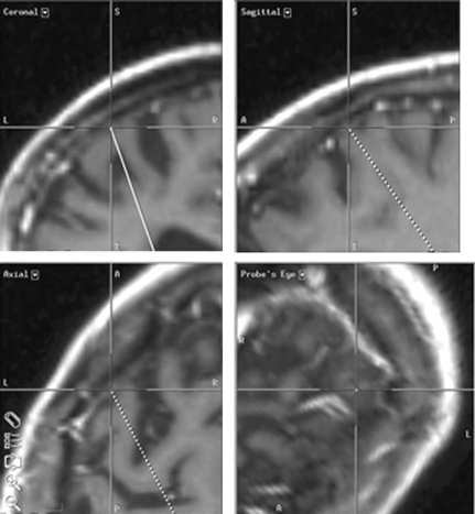
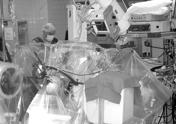
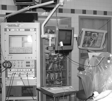
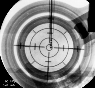
7 Stereotactic Surgery with Microelectrode Recordings Diane Sierens, Scott Kutz, Julie G. Pilitsis, and Roy A. E. Bakay Stereotactic surgery was developed to access and manipulate deep structures within the brain while minimizing trauma to the surrounding structures. The precision with which the target is reached is essential to accomplish this goal. We have found that use of both indirect and direct magnetic resonance imaging (MRI) targeting methods followed by electrophysiological confirmation with microelectrode recordings (MERs) yields precise results.1–3 Direct targeting is based on the use of radiological images that allow direct visualization of the target.2–13 However, MRI scans are not always of sufficient quality to visualize the target because nuclear boundaries are indistinct. Use of higher field strength 3 Tesla (tesla 3T) may improve the reliability of this technique.14,15 Indirect targeting can be the primary targeting method but more often it is complementary. Indirect targeting is based upon identification of the anterior and posterior commissures (AC and PC, respectively) and then using standard distances from the midcommisural point (MCP) of a line connecting them to approximate the location of a desired target. The distance between AC and PC may vary significantly between individuals, which limits the accuracy of this technique.16,17 However, direct targeting is not as accurate as initially believed, and indirect methods may be more accurate even when the target can be seen.18–24 MRI is highly susceptible to image distortion. Although the degree of error can be estimated by phantom studies, individual patient correction may be attempted by MRI fusion with computed tomography (CT). Image fusion does not eliminate errors.25 Regardless of the targeting method, errors are introduced (see Chapters 5 and 8 for nuances). This chapter describes the use of MER to definitively localize the stereotactic target intraoperatively by electrophysiological means. The microelectrode had been invaluable in allowing the precise identification of neural structures in the immediate vicinity of the electrode tip.1–3,26 In 1961, Albe-Fessard et al27 provided the first report of electrode recordings obtained from humans during stereotactic surgery. During that decade, the technique was incorporated by many others to define the borders of anatomical structures and targets during stereotactic procedures.28–30 Currently, the science of MER has advanced to the point where it is considered a routine technique in stereotactic and functional neurosurgery. Bertrand, Jasper, and coworkers31–33 were probably the first to record single units in the human thalamus. Many groups have described MER activity of the human thalamus and consider it a routine technique for thalamotomy or thalamic deep brain stimulation (DBS).1,34–41 Multiple functional neurosurgical centers that perform pallidotomy and pallidal DBS routinely use MER.2,42–67 The first case report of subthalamic nucleus (STN) DBS was published in 1994 by Benabid et al, who described a unique approach to the use of MER for optimizing lead placement.68 Although quality results can be obtained by experts with other electrophysiological techniques (see Chapter 8), the majority of investigators experienced in performing STN DBS surgery today use MER as the definitive targeting method.3,7,69–78 Reports of sustained improvements based upon long-term follow-up of greater than 1 year after bilateral DBS for movement disorders are predominantly from centers that use MER guidance.79–83 Thus, although there is no scientific proof of the utility of MER, it is the preferred method of most functional neurosurgeons. The success of the operation is often dependent on the close communication between the stereotactic neurosurgeon, the anesthesiologist, and the movement disorders neurologist. Other personnel would ideally include a neurophysiologist and a physician extender specializing in movement disorders. Before surgery, all medical and psychiatric problems must be resolved (see Chapter 4). Antiparkinsonian medications are withheld 12 hours prior to surgery to obtain an “off” state for evaluation at surgery. Most patients are uncomfortable with the thought of prolonged periods in the off state, but they must be encouraged not to take their antiparkinsonian medications to avoid drug-induced dyskinesias, which could interfere with stereotactic frame placement, proper imaging, and MER. Furthermore, improvements in clinical symptoms intraoperatively are useful to confirm accurate lead placement. This improvement is masked by antiparkinsonian medication. It also alters the firing rates, which lessens the value of MER. In patients with Parkinson disease (PD), apomorphine significantly decreased the overall firing rates of globus pallidus internus (GPi) neurons, but there was no change in the overall firing rate of neurons in the STN.84 We allow patients to take medications unrelated to their movement disorder with a sip of water on the morning of surgery. Typically, the patient is admitted to the hospital the morning of the procedure. An intravenous infusion line is inserted in the patient’s arm ipsilateral to the side of surgery, or the first side if bilateral. This allows for unimpeded movement of the contralateral extremity during intraoperative neurological examination. A short half-life drug such as propofol, remifentanyl, or dexmedetomidine may be used for frame placement and image acquisition. We use predominantly the Leksell series G (Elekta, Atlanta, GA; www.elekta.com/healthcare international stereotactic neurosurgery.php). Proper alignment of the frame with the patient’s anatomy simplifies targeting adjustments, allows consistent angles of approach, and decreases error that can be introduced by correcting for malposition. Although there are algorithms and computer imaging software that can correct imperfect alignment, each manipulation adds to the potential for inaccuracy. The ear-bars that are provided with either the Leksell or the Cosman-Roberts-Wells (CRW)-fn frame (Integra Radionics, Burlington, MA; www.radionics.com) prevent sideward tilt (roll) or axial rotation (yaw) of the frame relative to the patient’s head while permitting the pitch of the frame (anteroposterior axis) to be set so that the base ring lies roughly parallel to the AC—PC plane (Fig. 5.2). For the axial MRI to lie coplanar with the AC—PC, the frame needs to be parallel to a line from the inferior orbital rim to the external auditory canal. Foam pads or strips to the ear-bars can decrease the patient discomfort but must not distort the alignment. Use the ear-bar holes that are closest to the frame’s base ring and adjust the ear-bar base to center the patient in the frame. The fixation pins should not extend beyond the margins of the vertical posts so that the frame will fit within the confines of the scanner’s head coil. Opposing pins should be applied simultaneously to reduce the frame rotation; once engaged the ear-bars should be removed for patient comfort. The pins must be tightened enough to prevent slippage but not overtightened so as to distort the frame. When finished, the frame should be pulled on and any slippage or presence of pain suggests the need for further tightening. If the patient has kyphosis, the table adaptor will limit neck extension. Aligning the head more anteriorly in the frame and placing a pillow under the buttocks should correct this problem. Rarely, because of airway obstruction, endotracheal intubation is needed. The final and most important check is to have the MRI alignment beam symmetrically superimposed on both the lateral and the anterior fiducial channels of the localizer. MRI sequences and target coordinates are discussed in Chapter 5. It is preferable to perform surgery with minimal sedation. However, this may be difficult in children or adults with severe dystonia and therefore can require a general anesthetic (Chapter 6). Starr et al61 reported a case in which propofol was used as the anesthetic agent for a child with dystonia during MER. The pallidal discharges were depressed greatly. Krauss et al65 confirmed this finding. A better choice to avoid effects on spontaneous neuronal discharge is a mixture of ketamine and remifentanyl. We have also had success with dexmedetomidine. The stereotactic head frame typically renders the airway difficult to access for the duration of the procedure so that if general anesthesia is to be used it should be started before frame placement.85,86 Furthermore, the effects of any sedation given for the frame placement, image acquisition, or burr hole placement must be resolved prior to MER for which an awake, alert patient is essential for optimal recordings.1–3 Perioperative antibiotics, antibiotic-containing irrigation solutions and careful attention to sterile technique appear to be instrumental in maintaining a low infection rate. Hood et al87 performed 365 consecutive intracranial stereotactic procedures over a 6-year period with only three postoperative infections. Similar to other meta-analyses of antibiotic prophylaxis for prosthetics, a systematic review of antibiotic prophylaxis for surgical introduction of ventricular shunts clearly demonstrated the utility of systemic antibiotics in preventing shunt infections.88 In light of this, we use perioperative cephalosporin or vancomycin if the patient is allergic to penicillin. The use of prophylactic anticonvulsants is controversial and has not been studied in DBS to date. Although Shrivastava et al89 give patients a loading dose of phenytoin, we and others90 do not because seizures are rare and allergic reactions are common. We do not use corticosteroids. Intracranial hemorrhage is a well known and potentially devastating complication of stereotactic surgery. Careful control of perioperative blood pressure is important and may reduce the occurrence of this complication.91 Because hypotensive patients can become hypertensive in surgery, continuous blood pressure monitoring and the use of intravenous antihypertensive medications should be encouraged to keep systolic blood pressure less than 140 mm Hg or a mean arterial pressure below 90 mm Hg or both. An arterial line may be necessary. Also avoid all antiplatelet agents such as aspirin, nonsteroidal anti-inflammatory drugs, antiplatelet agents, or herbal supplements such as ginkgo, garlic, and ginger for at least 2 weeks prior to surgery. Anticoagulants require special preparation (see Chapter 5). Before starting surgery, the patient is positioned in a semisitting position with the side of initial surgery toward the anesthesiologist to allow the neurologist access to the contralateral side of the body during MER and test stimulation. Be aware that uncomfortable rigidity, akinesia, and off dystonia may become an issue intraoperatively after draping. Every effort to interact with the patient to provide optimal padding and neck positioning will pay off several hours into the case. It is important to attach the stereotactic head frame to the Mayfield headrest in a neutral neck position. Be sure that the Mayfield controls are readily available to adjust during the case as needed for patient comfort. The patient’s head is shaved according to the desire of the patient. Aziz et al92 do not shave the patient’s head, but they wash the hair with aqueous and then alcoholic chlorhexidine. We prefer to shave the entire head and drape so the patient’s face and eyes are visible on the nonsterile side of the drape. It is especially useful to mark the location of any hardware and thereby avoid damage to it during delayed second sides, reoperations, or in patients with other devices such as shunts. The eyes are only covered briefly during draping to minimize the patient’s sense of entrapment. Two sterile towels are folded into quarters that loop in the front and wrap around the base of the frame before placing the rings of the arc axes, and the operative area is covered with a 25 to 30 cm wide Ioban 2 (3M Health Care, St. Paul, MN; www.3m.com). The towels will keep the Ioban from adhering to the eyebrows or ears and protect the surgeon from potential contamination when placing the rings. We then use a clear plastic drape, either the Elekta stereotactic drape (www.ensproducts.elekta.com) for the Leksell, the Apuzzo stereotactic drape for the CRW (Integra Radionics; www.radionics.com/products/stereotaxy/), or the Ortho Bar drape (Kimberly-Clark Roswell, GA, http:// nacrm.kcmkt.com/ourbrands/ healthcare.asp) as a universal drape. The drape is then attached to an ether screen bar that can be angled as needed. A C-arm should be draped separately using sterile technique for intraoperative fluoroscopy. Many centers incorporate the drape with an overhead C-arm, but we prefer it to be independent and below the table to maximize mobility for aligning the fluoroscopic beam and ease of access to work above the frame. Infiltrating the incision line and reinfiltrating the four pin sites with 1% lidocaine and 1:100,000 epinephrine mixed with 0.5% marcaine in equal concentrations provides the patient with 6 to 8 hours of comfort. Some rapidly reversible sedation is frequently useful at the start of the procedure. We use a coronal incision 1 to 2 cm posterior to the proposed entry site to remove any tension on the suture line at closure. We take care to separate the pericranium so it can be used in the closure. After local infiltration, a large posterior and lateral subgaleal pocket is created with blunt dissection below the galea and above the temporalis fascia for the excess lead at the end of the case. Prior surgery or scars will require innovation and flexibility in the incision design. It is prudent to place the patient in a slight Trendelenburg position during the burr hole opening to reduce the possibility of air embolus. The team should realize that a venous air embolism will present differently in an awake patient and look for coughing, tachypnea, and hypoxemia.93 Prior to making a burr hole, surgical planning software and image fusion provides the technology to simulate the electrode’s trajectory and avoid blood vessels, sulci, eloquent structures, and, when possible, the ventricular cavity (Fig. 7.1). Surgical planning on the StealthStation using FrameLink (Medtronic Navigation, Louisville, CO; www.archive.stealthstation.com/physician/neuro/library/).jsp allows multiplanar imaging of the planned trajectory(s) with frame coordinates, and angles for the arc and ring are quickly and accurately calculated so adjustments can be made rapidly to maximize the safety of the tracts. To help prevent hemorrhagic complications, we give gadolinium prior to the three-dimensional T1-weighted MRI scan to enhance the vasculature and avoid superficial veins or sulci near the entry point. The burr hole should be placed anterior to the coronal suture. Inadvertent coagulation of a large draining vein anterior to the coronal suture will be more likely to be asymptomatic,91 but venous infarctions have been reported94 so it is best to plan a trajectory to avoid all visible vessels. Additionally, avoiding passage through sensitive cortex may minimize the incidence of postoperative epilepsy.90 Fig. 7.1 Surgical planning on the StealthStation using Framelink (Medtronic Navigation, Louisville, CO) allows multiplanar imaging of the planned trajectory(s) with routine axial, coronal, and sagittal planes in relation to the anterior—posterior commissure (AC—PC) plane and specific trajectory planes. Additional images, including magnetic resonance imaging (MRI) or computed tomography (CT) but not X-ray or ventriculography, can be fused by a best-fit technique, but it is not a true three-dimensional fusion. A Schaltenbrand and Wahren deformable atlas can be overlaid onto the brain image, but rarely is the fit good enough to use for surgical planning. Volumetric MRI with contrast allows a high degree of resolution in the reformatted images (orthogonal to AC—PC) and visualization of vessels as demonstrated in this photograph. A tract with an entry point that avoids the large superficial veins is planned. The section along the trajectory is indicated by the center of the crosshairs at the location that is being indicated in each plane. The probe’s eye view is perpendicular to the trajectory and allows the best view of the anatomical relationships along each slice. For STN, we plan the entry site slightly lateral to the eventual target (0 to 8 degrees). Otherwise we try to maintain a strict parasagittal approach. This allows the entire MER trajectory with the collected physiological data to be plotted on a single sagittal slice from a brain atlas and analyzed for target localization. At the same time, the slightly more lateral approach avoids penetration of the medial caudate and medial thalamus, damage of which is believed to be associated with possible cognitive impairment. Others prefer to place the burr hole 3 to 4 cm lateral to the midline and plan their trajectory of the probe to avoid penetration of the ventricular ependyma, which can deflect the MER or DBS lead.7,95 Typically this will result in a trajectory 50 to 60 degrees from the AC—PC line in the sagittal plane and a coronal angle 10 to 30 degrees from midline depending on ventricular size. This renders any rectilinear atlases useless. By restricting the coronal offset to 0 to 8 degrees the error is less than 1 mm through the target and will miss most ventricular walls. This is not always possible. In older patients where the shift after decompression of the ventricle can be significant, we will frequently use a more lateral approach to avoid the ventricles. If there is not a lot of atrophy, we do not have a problem going through the ventricle if need be, but realize that there can be deflections off of the ventricular wall. Fluoroscopic and anteroposterior (AP) radiographic imaging is most helpful in these cases (Fig. 7.2). Fig. 7.2 This photograph of the operating suite demonstrates a typical setup for electrophysiology and intraoperative radiography during neurosurgery for deep brain implantation in the treatment of movement disorders. A clear plastic barrier separates the patient from the operative field with complete sterility behind the barrier and yet allows the surgeon to view direct interactions between the patient and movement disorders neurologist. Intraoperative fluoroscopy is set up in anticipation of confirmation of both microelectrode and deep brain stimulation (DBS) tracts. Fluoroscopic equipment is covered with a separate plastic drape allowing complete mobility during the procedure while at the same time not impeding access to the headstage. A portable X-ray machine is brought in only after there is a lead in place to allow anteroposterior skull X-rays to help determine the distance between the implanted lead and the electrode or second DBS lead. A 14 mm burr hole is made and the diploe and inner cortical bone are undermined with a high-speed drill to form a cone that will maximize the microelectrode trajectories without striking dura or the bony edges of the burr hole. To secure the lead, we use the Stimloc from Medtronic Inc. The burr hole edge needs to be slightly enlarged from 14 to 15 mm to accommodate the Stimloc base and clip. When bilateral placements are planned, we drill the second side first but do not open the dura. If an unexpected dural vein is encountered, the hole can be expanded away from the vein to avoid opening the dura in that position. If that is not reasonable, a new hole is created. The dura below the Stimloc should then be free of venous structures. It is important to remove all visible dura to optimize probe exploration without deflection. The dura is cut in a cruciate manner and cauterized to expose the entire underlying cortex. Continuous irrigation is used to minimize cerebrospinal fluid (CSF) loss and pneumocephalus. Immediately after opening the dura widely, the pia-arachnoid is opened at the entry point to ensure smooth passage of the probe. The burr hole is filled with fibrin glue (Evicel; Johnson and Johnson Gateway, Somerville, NJ; www.Evicel.com) to reduce CSF loss and dampen pulsation artifacts during MER. If there is an unexpected cortical vein, we free it from the pia-arachnoid and push it aside before applying the fibrin glue to keep it out of the primary trajectory and avoid injury. If this is not possible or we still have concerns later in the case, we will remove the fibrin glue and visualize subsequent entries into the cortex before resealing the CSF space with fibrin glue. Now is a good time to stop all anesthetic agents except for blood pressure control. The Stimloc base is centered and attached to the skull with the groove for the lead pointing posterior and slightly laterally. A fractured screw can be replaced by a screw from a skull fixation tray rather than opening another Stimloc kit. Avoid putting screws into the coronal suture. At this point the risk of air embolism is small, and it is important to elevate the patient’s head to a semireclining position with knees bent for patient comfort. This also helps to avoid leakage of CSF and decreases the mechanical load of the micropositioner on the frame. Two observers should independently check all calculations and settings to avoid errors. Remember the “Left” or “Right” on the Leksell arc refers to the side the calibrations are on relative to the patient and not the side of surgery. We always use the left side to avoid confusion. Again, be sure not to overtighten the arc or distortion of 1 to 2 mm can occur. Also be careful to read the direction of the numbering. Failure to do so can result in approaching from the opposite side or recording from GPi rather than STN. All probes used must be carefully inspected for slight bends before each case. It is prudent to have a special case to store the guide tubes to prevent mishandling during the sterilization process. We replace all probes every 6 months to ensure rectilinear approaches. By this time, there are a tremendous number of points where errors can be introduced (i.e., malposition of the frame requiring corrections for pitch, yaw or roll, overtightening of the pins causing distortion of the frame, measurement limitations, inaccuracies of the frame, distortion from the MRI field, slice thickness, targeting errors, mechanical loading effects on the frame from positioning or headstage, brain shift from CSF loss, or decompression of the ventricles, etc.). The errors may effectively cancel each other out or they may be additive. The net effect is that the theoretical accuracy of stereotactic systems is rarely achieved, and significant inaccuracies can occur.96 There is then a need to correct for those errors before the lead is placed. MER is a neurophysiological technique that detects and amplifies the activity of individual neurons97 and that performs the following tasks: We record single-unit action potentials with tungsten or platinum-iridium-tipped microelectrodes with an impedance of 0.1 to 1 Mohm at 1000 Hz FHC, Brunswick, ME; www.fh-co.com/microelectrodes.html. Typically microelectrode recordings begin 20–30 mm above the proposed target. The depth of recording is determined by the length of the guide tube. Longer routes record more information about the approach but also could result in greater deviations. The amplitude, frequency, and pattern of action potentials are recorded. Due to the extreme fragility of the microelectrode, it must not be touched; when not in use it should be withdrawn into the guide tube. The electrode is advanced in a precisely controlled manner with a micropositioner system. Several systems are commercially available such as Guideline System 4000 Clinical Micropositioner (FHC, www.fh-co.com; FHC Micro-Drive, FHC, Brunswick, ME; www.fhco.com/microtargeting.html); Nexdrive, Medtronic (www.medtronic.com), Stereoplan with NeuroMap (Integra Radionics, Burlington, MA; www.radionics.com) and Microguide microelectrode recording system manufactured by Alpha-Omega Instruments, Nazareth Illit, Israel, MicroGuide (www.alphaomega-eng.com).2,98,99 They all provide signal amplification, filtering, visual displays, audio monitoring, impedance monitoring, and stimulation. The Axon micropositioner has an X-Y stage that permits precise movement in the anteroposterior and mediolateral directions. The FHC, Nexdrive, and MicroGuide have five channels separated by 2 mm, and depending on the orientation and 3 mm offset, allow for 49 separate tracks. Nexdrive now has grids to reach anywhere in a 1 cm × 1 cm area. The recording system must distinguish single-unit action potentials from background neural activity and extraneous electrical noise. Fluorescent lights, heaters, operating room (OR) table motors, and all electrical devices (bipolar, Bovie, etc.) are turned off or unplugged. All OR monitoring equipment that contacts the patient should be battery powered to minimize potential interference with electrophysiological recordings. Electrical noise can range from 1 mV to > 1 V if the patient is not properly grounded.98 The microelectrode guide tube is an excellent ground. High (> 200 Hz), low pass (< 2 Hz), and adaptive noise filters are used, and there is almost never a need for a notch filter (60 Hz). The neurophysiologist and/or neurologist and neurosurgeon interpret the signal once it is optimized. This is done by examining both visual and auditory amplifications of the local neural electrical output. Due to the rapid appearance of spikes across the screen, the ear can distinguish small changes in the neural signal better than the eye. A good auditory amplifier and trained ear are essential for properly interpreting MER. Headphones are not necessary. There is only one opportunity to correctly evaluate a tract. The microdrive is essential to slowly transverse the tract. Moving too quickly through an area will miss boundaries and opportunities to interrogate cells. Fig. 7.3 On the left, the intraoperative microelectrode recordings (MERs) are processed and the data stored in an Axon Guideline 3000A (Frederick Haer Co., (FHC), Brunswick, ME). All data and spike sorted imaging can be viewed simultaneously. On the right, this information can also be shared with the StealthStation Treon (Medtronic Navigation, Louisville, CO). Sophisticated trajectory planning can be made on the StealthStation. The data can be annotated along with trajectory to allow electrophysiology data and anatomical data to be compared. Unfortunately, there is no way to link the anatomical database with electrophysiology at this time. The data can be stored for later review. Fig. 7.4 Intraoperative fluoroscopy of a five microelectrode recording (MER) approach to the subthalamic nucleus is shown. The nucleus has been mapped and the medial microelectrode had the longest and most active tract. This electrode has been removed and the deep brain stimulation lead inserted in its place. The guide cannulae of the other four microelectrodes act to “fix” the brain in place to help maintain spatial accuracy and prevent “brain shift” before lead placement. We use the Axon Instruments Guideline System 3000A (distributed by FHC, Brunswick, ME) (Fig. 7.3) and are testing multiple MER systems (Fig. 7.4). There are several systems available for multiple simultaneous MERs (i.e., Alpha Omega Microguide system, Medtronic StimPilot, and FHC microtargeting drive system). The multiple MER systems appear to allow greater amounts of data to be more efficiently obtained. This has been our experience with either two, three, or five microelectrodes. Whether single or multiple MERs are used, the number of tracts needs to be sufficient to ensure the optimal target. This decision is based on experience and the art of functional neurosurgery. There is the strong but unproven belief that the fewer the tracts the safer the procedure. The rate of symptomatic hemorrhages between single and multiple MERs is similar, with an incidence of 1 to 3% (see Chapter 8). For DBS this low rate is expected. Furthermore, many centers using five simultaneous MERs have few complications and excellent efficacy.82 It is not likely that results will vary based only on the number of microelectrode penetrations. We primarily use multiple single MER tracts but are increasingly testing multiple (simultaneous) MER and prefer three tracts to obtain maximum information with minimal trauma.
Operative Techniques and Patient Positioning
Microelectrode Recording
| ROOM | Headstage |
| ELECTRODE | |
| Fluorescent lights | Too high impedance |
| Bovie | Too low impedance |
| Bipolar | Damaged or bent tip |
| Metal to metal contact on the frame | Poor contact |
| Electrocardiogram | |
| PATIENT | GROUND |
| Improper location | |
| Cerebrospinal fluid pulse artifact | Poor contact |
| Headstage movement | CABLE |
| Patient speaking or coughing | Wire damaged or broken |
| Failed shielding | |
| Crossed wires |
We and others98 routinely perform microstimulation to “condition” the microelectrode to enhance its recording performance. Sometimes the sterilization process can leave a layer of oxidative by-products on the electrode, which interferes with MER. A short burst of current (25 to 40 μA, 500 μs, and 300 Hz) “cleans” the electrode tip. Frequent impedance checks to keep it in the 0.3 to 0.6 Mohm range are performed throughout a tract, and the cleaning process may need to be repeated. The patient must be completely awake during recording because stupor will dramatically suppress the electrical activity. During the recording of single units, the microdriver is paused and the contralateral body is manipulated to trigger firing of neurons that respond to either active, passive, or tremor movements called sensorimotor responses. In all structures, we search for kinesthetic responses to passive movements about joints or voluntary movements. In the thalamus, we also search for responses to light touch, deep pressure, and hot/cold stimuli. At the end of the pallidal tract, if visual responses are expected due to proximity to the optic tract, a bright light (fiberoptic cable works best) is flashed back and forth into the eyes. Just as important in plotting the map are the quiet areas. These can be used to clearly define nuclei even when the individual unit activity is unclear or not present due to poor recordings or general anesthesia. Also very useful is the recognition of cellular background or neural noise (the primary function of semimicroelectrodes). The increased activity that occurs when a nucleus is entered and lost when exited is similarly helpful in defining boundaries parallel to the quiet areas. Increased background can be heard and seen. Thus, even if no action potentials are recorded for a good length of time, as long as the background is active the nuclear boundary has not been crossed, nor should a lamina be suspected as long as the volume setting is unchanged.
There are many possible artifacts that can occur (Table 7.1). Mechanical artifacts are common and frequently misinterpreted by the inexperienced examiner (Fig. 7.5). A little blood on the MER or guide tubes is meaningless but unexpected electrical silence should raise the suspicion of hemorrhage, and careful clinical evaluation is mandated. Isolation of individual neurons is optimal but not essential for interrogation of sensorimotor responses. Passive and active joint movements should be sought in a systematic fashion. Assessment of the movement-related neuronal activity provides important information in isolating the motor territory. Movements should be vigorous and any increase or decrease in firing rates should be confirmed by reexamination at a later time. Always doubt any positive results and try to prove them wrong. Fast firing rhythmic neurons and bursting cells can present a problem for interrogation. Rhythmic movements of the joints may result in false-positive conclusions of kinesthetic response, and irregular movements of the joints may be needed to bring about a correct conclusion.
Intraoperative Testing
During MER, data are gathered and the physiological information is annotated on the corresponding stereotactic atlases.100,101 Maps such as the Schaltenbrand and Wahren atlas were not prepared using brains of patients with severe movement disorders and may not represent the true anatomical mapping in this group of patients, but it is the best map available to date.102 Precise mapping of any target nucleus often requires multiple trajectories to complete the electrophysiological map and determine the best fit. Just because the frame is set at 11 or 20 mm from midline does not mean the map will fit on the atlas at 11 mm or 20 mm. The individual variability must be form fitted so the MER and the atlas align reasonably well. Thus the anatomical 20 mm location may fit best at 21.5 mm by the electrophysiology. At the conclusion of each track, we perform microstimulation with the same microelectrode starting at 5 μA and increasing up to 100 μA (biphasic pulses) to elicit responses. Localization of the optimal target is followed either by the insertion of a radio frequency (RF) probe and generation of a lesion or by insertion of the DBS lead. Macrostimulation is then performed to physiologically confirm the anatomical target prior to lesioning or stimulator placement. Intraoperative stimulation tests for efficacy and confirms lack of side effects to an acceptable threshold. Intraoperative neurological examination may demonstrate functional improvement of the patient during MER, lesion generation, or lead placement, which is a good indicator of the ultimate clinical outcome. We will describe the typical neurophysiological characteristics of the thalamus, GPi, and STN.
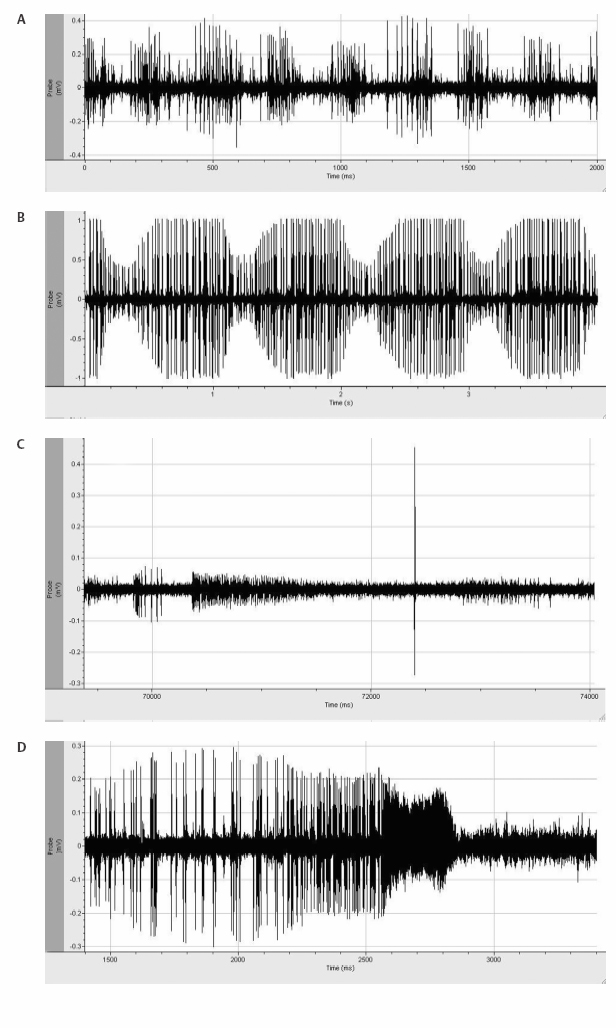
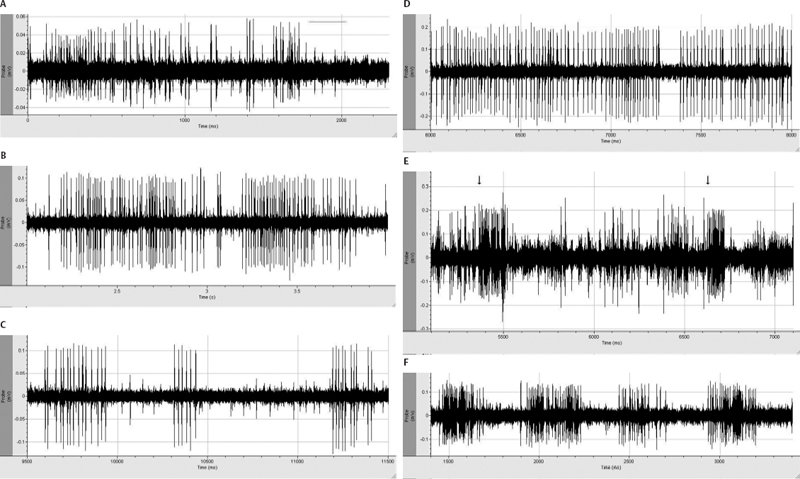
Fig. 7.5 Several unusual electrophysiological tracings are demonstrated in this figure: (A) Mechanical artifact is demonstrated in this electrophysiological tracing. The intermittent increase in activity represents an artificial increase in the action potential height of a poorly isolated cell in relation to mechanical effects of tremor on the frame. (B) Pulse artifact is demonstrated with a rate that will parallel the electrocardiographic tracing. (C) Insertional activity is demonstrated in the striatum. The initial activity from inserting the microelectrode initiates action potentials, which gradually fade. In addition, there is fiber activity seen as a very large action potential. If this were to be placed on a longer time scale, one would see that the wave form of the fiber is inverted. (D) Mechanical injury potential with loss of membrane integrity and rupture of the cell leading to aberrant action potentials followed by silence.
Thalamic Microelectrode Recordings
Using the sagittal diagrams of the human brain from the Schaltenbrand and Bailey atlas,101 the anatomy of the thalamus can be defined (see Chapter 11) with the ventralis intermedius nucleus (Vim) being the target (Fig. 11.5). This is a small (2 mm wide) subnucleus. The target is the hand area at the Vim and ventralis oralis posterior (Vop) border (~6 mm anterior to the PC, 10 to 10.5 lateral to the third ventricular wall, and in the AC—PC plane). This is an ill-defined target on MRI (Fig. 11.6). The optimal angle is 60 degrees from the AC—PC to parallel the Vim and Vop subnuclear borders. Notice that the ventralis caudalis (Vc) nucleus constitutes the relay for sensory or tactile stimuli transmitted in the medial lemniscus.26 Interestingly, neurons in the dorsal portion of the Vc and central and dorsal nuclear subdivisions that lie more superiorly in the thalamus do not respond to any known stimuli. Caudal Vc (ventracaudalis parcocellularis externus, Vcpe) is identified when highamplitude evoked responses are obtained when the contralateral body is lightly touched. Low threshold (5 to 10 μA) microstimulation resulting in a precise paresthesia will help to confirm the location, as opposed to the medial lemniscus, which produces widespread paresthesia (hemiparesthesia or whole limb). Just anterior to the Vc is what has been described as the “shell” nucleus (ventrocaudalis anterior externus, Vcae), which responds best to deep pressure.1 The Vc nucleus serves as a “navigational landmark,” and MER movements are based on this information (Table 7.2).
The somatotopic organization of the thalamus has been well described with the lower-limb sensory neurons lying more laterally (14 to 16 mm) than hand (14 to 12 mm), or mouth (12 to 10 mm), and more medially no kinesthetic cells can be recorded.1,38 We prefer to target the Vc and by advancing through the Vim (26 ± 4 Hz) identify both in the first pass (Fig. 11.4). Bursting cells synchronous to tremor are a significant feature of the Vim. Immediately anterior to the Vim is the Vop (18 ± 3 Hz), which represents the pallidothalamic relay.26 “Tremor” cells can also occur in Vop but are infrequent. Another potential difference between the two is the kinethetic (movement sensing) response: Vim cells respond primarily to passive movement and Vop cells respond primarily to active movement of contralateral joints (voluntary cells). Our second pass is 2 to 4 mm anterior to the first to identify Vim/Vop and determine the bottom of the thalamus. If we have a dual MER setup, we target 4 mm apart in AP (2 and 6 mm anterior to PC) with the anterior MER at target.
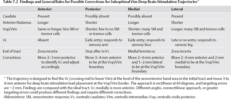
Certain pitfalls should be kept in mind when one is exploring the thalamus. The posterior ventromedial nucleus (Vmpo) has been shown in the monkey to receive direct inputs from spinal cord lamina I nociceptive and thermoreceptive neurons.103 This ventral nucleus is located at the inferoposterior rim of the Vc, and neurons may respond to warm, cold, or noxious stimuli. The Vmpo nucleus overlaps with the Hassler parvocellular Vc (Vcpc) nucleus.104 Interrogation and stimulation of this area can confuse less experienced investigators because the somatotopy is not the same as the Vc. Another pitfall is that quiet areas in the body of the thalamus may exist due to previous brain lesions, trauma, or infarcts. These lesions may disrupt the homuncular arrangement.26 The bottom of the thalamus is usually clear with loss of background activity and only infrequent neurons recorded in the zona incerta (Zi) or fibers of the medial lemniscus. The key to success is to find the appropriate somatotropic area of the Vc and put the lead 3 to 4 mm anterior to it. Microstimulation (60 to 100 μA, 500 μs, and 300 Hz) can frequently but not reliably decrease tremor, so primarily we look for side effects. If positive, the MER is < 2 mm from the Vc or capsule, and a move is necessary. If negative, it is not informative. Additional details can be found in Chapter 11.
Globus Pallidus Internus Microelectrode Recording
Using the sagittal diagrams of the human brain ~20 mm from the midline based on the Schaltenbrand and Bailey atlas,101 the anatomy of the GPi can be defined (Fig. 7.6). It is a lens-shaped nucleus ~500 mm3 (Fig. 7.7). The optimal angle is 45 degrees from the AC—PC. The initial trajectory is the ~3 mm anterior to the MCP, 17.5 mm lateral from the third ventricular wall (the equivalent of lateral 20), and 4 to 6 mm below the AC—PC plane.2,6 A typical first microelectrode trajectory courses through the striatum (putamen), the globus pallidus externus (GPe), and finally the GPi. Ventrally beyond the GPi, the electrode crosses the pallidofugal axons (ansa lenticularis) and enters the optic tract. Because of the importance of finding the optic tract, adjustments are made to directly target the lateral edge of it on the first tract even if it is 19 or 18 mm lateral on coronal T1 images to assure this trajectory identifies this landmark (Fig. 7.8). The striatum shows a tonically active slow rate of firing, ranging from < 1 to 6 Hz. It frequently exhibits insertional activity that quickly fades, leaving only faint noise of background activity. Passage through the lateral medullary lamina, the background activity is quiet with rare border cells or fibers. Border cells fire regularly at 30 to 40 Hz, do not have receptive fields, and do not respond to movements.2 When entering the GPe, the background increases due to neural activity. Both the rate and the firing pattern will vary in GPe and GPi with the disease process and state of alertness.2 Two types of GPe neurons are identifiable (Fig. 7.9). Most GPe neurons “sputter” with irregular pausing patterns with a firing rate of 50 ± 21 Hz. Rates may be slower with hyperkinetic disorders. About 10 to 20% of GPe neurons fire at low frequency (18 ± 12 Hz) with high-frequency, short duration bursts. Kinesthetic responses are not generally observed in the trajectories used for this approach, because they reside in the posterior putamen. As the electrode leaves the GPe, the medial medullary lamina is crossed, which is a 1 to 3 mm wide band of fibers characterized by the absence of somatodendritic action potentials and no neural background activity (electrical silence except for background noise). If too lateral, this lamina is 4 to 6 mm thick. This is a key finding and will assist separating the GPe from the GPi even under general anesthesia. The accessory medullary lamina partially divides the GPi into inner and outer subdivisions. Again, this will assist in determining laterality. A short GPi and large accessory medullary lamina should not be confused for the internal medullary lamina and a too lateral plane. A posterior move will make the lateralization clear. At the periphery of the GPi in any of the lamina, border cells frequently occur. Border cells are believed to be aberrantly located neurons of the nucleus basalis of Meynert.2,105 A very large number of these cells at the end of a tract suggest far anterior location in the basal forebrain.
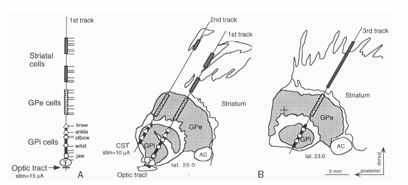
Fig. 7.6 Microelectrode mapping from a case of globus pallidus internus (GPi) is demonstrated. (A) The first track is directed toward the optic tract. Detailed findings are represented on the left. Nuclei, lamina, kinesthetic cells. and optic tract are recorded. (B) The microelectrode reconstructions are superimposed on sagittal drawings of the Schaltenbrand and Bailey atlas. The open rectangle segment represents putamen, the gray-shaded segments represent external pallidal activity (GPe), and the black-shaded segments, internal pallidal activity (GPi). Light-evoked action potential discharges (LED) were recorded 1 mm below the exit from the GPi at the end of track 1. We would place the deep brain stimulation lead 1 mm lateral and 0.5 mm anterior to track 1 to get further away from the corticospinal tract. The lead would terminate at the ventral border of the GPi. CST, corticospinal tracts. Adapted from Starr et al with permission.3
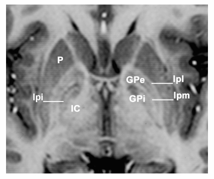
Fig. 7.7 Magnetic resonance imaging demonstrates an axial section in the anterior—posterior commissural plane. The globus pallidus is well demonstrated. Between the putamen (P) and the globus pallidus externa (GPe) is the lateral medullary lamina (lpl or Hassler’s lamina pallidi lateralis) and between the GPe and globus pallidi interna (GPi) is the medial medullary lamina (lpm or Hassler’s lamina pallidi medialis). Medial and posterior to the GPi is the internal capsule (IC). On the patient’s right side in addition to the two laminae surrounding GPe, an additional lamina within the GPi, the accessory medullary lamina (lpi or Hassler’s lamina pallidi incompleta) is present. Hassler used lpi to divide GPi into pme and pmi, but that only serves to unnecessarily confuse the nomenclature.
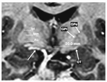
Fig. 7.8 Coronal magnetic resonance imaging at the level of the mammillary bodies demonstrating the globus pallidus externus (GPe) and internus (GPi) with the lateral (lpl) and medial (lpm) medullary lamina surrounding the GPe and the ansa lenticularis (AL) at the base of GPi. The optic tract (OT) is seen well on both sides allowing direct targeting. The patient’s right side demonstrates a blood vessel (unmarked arrow), which can frequently accompany the optic tract in the ambient cistern and must be avoided. If the optic tract is not encountered within 1 to 2 mm of the anticipated location, it is not pursued deeper when a vessel is in the area.
In PD, GPi neurons fire faster than GPe neurons at 82 ± 24 Hz with a less irregular discharge pattern and shorter pauses. Vitek et al2 report that other patterns may be present such as high-frequency bursts or activity with little pauses between the bursts, creating a “chugging” sound, or lower frequency bursts in the range of 4 to 6 Hz in patients with PD. The 4 to 6 Hz pattern may or may not be associated with overt tremor. The optimal target within the globus pallidus has been a subject of debate.106–111 The target most commonly used today is the posteroventral GPi.108 The same target is used for dystonia but the rates of firing of GPe and GPi are similar, and careful attention to boundaries is essential.112 Additional details on dystonia can be found in Chapter 12. The sensorimotor area resides in the most posterior and lateral region of the GPi. The sensorimotor territory is bounded by the ambient cistern and the optic tract ventrally and the internal capsule at the posterior and medial borders. The manipulation of the individual joints of the contralateral body will localize the sensorimotor territory of the GPi (Fig. 7.10). Approximately 25% of neurons in the posteroventral portion of the GPi respond to kinesthetic movements, and many will respond to multiple joints. The GPi is somatotopically organized with the lower extremity represented more medial and dorsal than the upper extremity.2,60,113–115 This is the inverse of Vim but similar to STN. The jaw representation is found more ventrally. With adequate sampling (4–6 kinestetic cells), the GPi somatotopy can be trusted in helping determine laterality.
Related posts:


Stay updated, free articles. Join our Telegram channel

Full access? Get Clinical Tree


