, Damien Gervasoni1 and Catherine Vogt2
(1)
Lyon Neuroscience Research Centre CNRS UMR 5292–INSERM U 1028, Université Claude Bernard Lyon 1, Lyon, France
(2)
Université Claude Bernard Lyon 1, Lyon, France
“Stereotaxy” is defined as “a method in neurosurgery and neurological research for locating points within the brain using an external, three-dimensional frame of reference usually based on the Cartesian coordinate system” (American Heritage Dictionary of the English Language http://www.ahdictionary.com/word/search.html?q=stereotaxy). Stereotaxic surgery has thus been described as “the introduction of instruments, or the direction of radiation beams into a small, well defined but invisible target within the skull… to explore the functional properties of this target, to biopsy it or to alter it by physical or chemical means” (De La Porte 1993).
The stereotaxic approach implies a knowledge and understanding of the anatomical and functional characteristics of brain structures, the spatial coordinates of the target, and the basic principles of surgery related to anesthesia, analgesia, and asepsis. The quality of the end result of the operation and its reproducibility depend on the respect of a precise and rigorous procedure. The principal notions necessary to undertake this type of surgery are closely associated with regulatory, bibliographic, technical, and mathematical aspects.
4.1 The Stereotaxic Atlas
The implantation of cannulae, electrodes, or other instruments into a given brain structure requires a knowledge of the theoretical coordinates of implantation. It is the responsibility of the user to be particularly vigilant as to the adequacy of the stereotaxic coordinates shown in a published atlas and those that should otherwise be verified and validated for use in his/her own experimental model.
In this regard, the body weight, sex, species, strain, and age of the animals to be operated are critical factors to be taken into account in order to adjust the stereotaxic coordinates proposed by an atlas, which are specified for a particular strain of the species and weight. The investigator should be aware of the peculiarities specific to each atlas and to choose the one best suited to his/her needs.
Several stereotaxic atlases of the rat and mouse brain are currently available. Since these atlases use different cartographic parameters, the coordinates determined using one atlas are valid only for that particular atlas The examples of coordinates cited in this guide are based on the atlas of Paxinos and Watson (4th edition, 1998 and 5th edition, 2004).
4.1.1 Stereotaxic Atlases
4.1.1.1 Rat
Different atlases listing the brain structures in the rat can be found. Some of them are listed below:
König JFR, Klippel RA (1963) The rat brain: a stereotaxic atlas of the forebrain and the lower parts of the brain stem
Albe-Fessard D, Stutinsky F, Libouan S (1966) Atlas stéréotaxique du diencéphale du rat blanc
Pellegrino LJ, Cushman AJ (1967) A stereotaxic atlas of the rat brain
Cooley RK (1990) Stereotaxic surgery in the rat: a photographic series
Altman J, Bayer SA (1994) Atlas of prenatal rat brain development
Swanson L (2003) Brain maps: structure of the rat brain
Paxinos G, Watson C (1998) The rat brain in stereotaxic coordinates, 4th edn
Paxinos G, Watson C (2004) The rat brain in stereotaxic coordinates, 5th edn
Paxinos G, Watson C (2007) The rat brain in stereotaxic coordinates, 6th edn
Paxinos G, Watson C (2013) The rat brain in stereotaxic coordinates, 7th edn
4.1.1.2 Mouse
Different atlases listing the brain structures in the mouse can be found. Some of them are listed below:
Sidman RL, Angevine JB Jr, Taber PE (1971) Atlas of the mouse brain and spinal cord
Montemurro DG, Dukelow RH (1971) A stereotaxic atlas of the diencephalon and related structures of the mouse
Lehmann A, Gautier M, Ghilini G, Henry J, Langlois R, Laplante S (1974) Atlas stéréotaxique du cerveau de la souris
Schambra UB, Lauder JM, Silver J (1991) Atlas of the prenatal mouse brain
Paxinos G, Franklin KBJ (2001) The mouse brain in stereotaxic coordinates, 2nd edn
Paxinos G, Franklin KBJ (2003) The mouse brain in stereotaxic coordinates: compact, 2nd edn
Franklin KBJ, Paxinos G (2008) The mouse brain in stereotaxic coordinates, 3rd edn
Paxinos G, Franklin KBJ (2012) The mouse brain in stereotaxic coordinates, 4th edn
4.2 The Stereotaxic Apparatus
The stereotaxic apparatus comprises a U-shaped stereotaxic frame mounted on a baseplate. Three mechanical elements (microdrives) fixed upon the frame allow travel of an electrode (or cannula) holder along three orthogonal axes: forward and backward, up and down, and side to side (Fig. 4.1). This micromanipulator assembly is fixed to the side of the frame and can be moved in three dimensions by three micrometric vernier screw drives. Three points are used to fix the head of the animal in the frame: two laterally adjustable ear bars and a height-adjustable incisor bar.
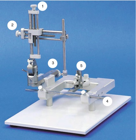
Fig. 4.1
Stereotaxic frame equipped with a micromanipulator. (1) Microdrive screw adjustment of the dorso-ventral axis; (2) microdrive screw adjustment of the mediolateral axis; (3) microdrive screw adjustment of the antero-posterior axis; (4) ear bars to center the head parallel to the antero-posterior axis of the frame; (5) incisor bar, which determines and fixes the plane of inclination of the head in the “flat-skull position,” such that the bregma and lambda points are located on the same horizontal plane, i.e., to have the same dorso-ventral coordinates
Commercially available stereotaxic devices are designed for a given species. There are several that exist for the rat, including those provided by ASI Instruments®, Narishige®, Kopf®, and Stoelting® (Fig. 4.2). For the mouse, there are complementary adaptable frames from Supertech Mouse® and Cunningham Mouse® (Fig. 4.3), which can also be used for small rats. In each case, three microdrives allow for a very precise travel in three-dimensional spaces, owing to the three vernier scales mounted on the frame (Fig. 4.4).
In this way, it is possible to move along the antero-posterior “y” axis (AP), which describes a line running from the anterior to the posterior part of the animal’s head; the mediolateral “x” axis (ML), which runs from the midline to the right or left side of the head; and the dorso-ventral “z” axis (DV), which runs from the surface of the skull towards the interior of the brain.
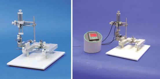
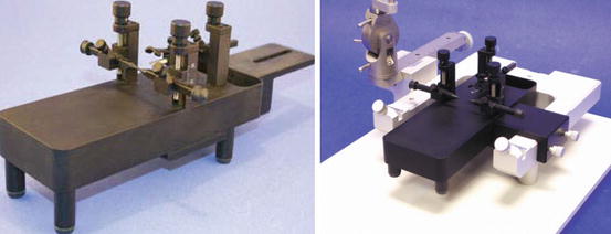
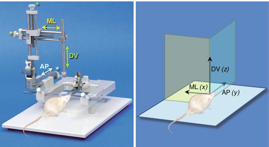
Fig. 4.2
Standard stereotaxic frames from Stoelting®, equipped with a manual (left photo) and a digital micromanipulator (right photo) for surgery on rats
Fig. 4.3
Examples of standard stereotaxic frames from Cunningham®, used alone (left photo) or placed in a Stoelting®-type apparatus equipped with a manual micromanipulator (right photo) for surgery on mice or small rats
Fig. 4.4
Representation of three micromanipulators in a stereotaxic apparatus (left figure) that allow movement in a three-dimensional space represented by the x, y, and z axes (right figure). AP antero-posterior, ML mediolateral, DV dorso-ventral
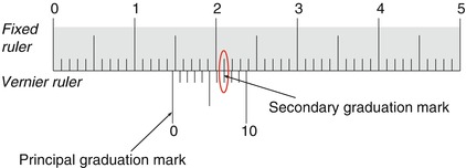
The amplitude of travel of each of the three micromanipulators is typically 80 mm. Each micromanipulator consists of a graduated movable arm which travels along a dovetail slide on the fixed arm of the stereotaxic apparatus. The first part of the vernier consists of a graduated scale extending from 0 to 80 (Fig. 4.5) situated on the movable arm. The second portion of the vernier, situated on the fixed part of the arm, consists of a “window” with graduations, from 0 to 10, set 0.9 mm apart. The “0” mark, or principal graduation mark, gives the coordinate reading to the nearest millimeter; the secondary graduation mark on the vernier that lines up with one of the marks on the fixed ruler then gives the reading in tenths of a millimeter.
In this way, the operation of the vernier establishes with precision the distance traveled in one direction or the other. The method of reading the measures on each vernier on the AP, ML, and DV axes is the same.
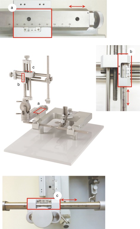
Fig. 4.5
Stereotaxic apparatus and details of three verniers located on the antero-posterior (a), mediolateral (b), and dorso-ventral (c) micromanipulators. A good working knowledge of the vernier is essential for accurately determining the coordinates of the point that you want to target in space. The end of each arm is equipped with a set screw that allows forward or backward transit according to the indications on the vernier
4.2.1 Stereotaxic Precision: Description of How the Vernier Works
Most stereotaxic devices have an accuracy of 100 μm obtained by means of a vernier. Invented by the mathematician Pierre Vernier in the seventeenth century, the vernier can improve the precision of various analogic measuring instruments, such as a caliper, a device used to measure the distance between two opposite sides of an object, and the goniometer, which measures an angle or allows an object to be rotated to a precise angular position. One can find different types of verniers on stereotaxic devices.
In variant 1 in Fig. 4.6, the reading shows 14.7 mm, that is, a point between 14 and 15 mm on the fixed ruler as read by the principal graduation or “0” mark and 7/10 of a millimeter according to the secondary graduation that aligns with one of the graduations on the fixed ruler. A vernier can move along this graduated rule in both directions. Reading is performed in the same way as described above, first with the principal graduation mark then with the secondary graduation mark. The reading of the vernier scale follows the direction of the fixed ruler.