Thoracoscopic Approach
Overview
For the surgery of thoracic spinal tumors, open thoracotomy is usually used. However, morbidity associated with conventional open thoracotomy often limits the application of anterior approaches to the thoracic spine. Most of the vertebral body tumors of the thoracic spine involve the anterior column; these tumors require rib removal and parietal pleura opening, which can cause complications, such as postthoracotomy syndromes and intercostal neuralgia. Open thoracotomy also requires extensive exposures, and incisions measure up to 20 cm. In recent years, minimally invasive open microscopic approaches using special retractors have been developed that can minimize the size of the operative access to 6 to 10 cm. These “mini approaches” are quite feasible in surgery on the upper and midthoracic spine. The limited working space available through small incisions may block the microscopic view and result in difficult manipulation of instruments. However, video-assisted thoracic surgery (VATS) using four portals in the chest wall permits surgery that is as effective as the open approaches, and it provides a better view than the microscopic one. Unlike the open approaches, the surgeon’s operative view is not obscured by hands or operative instruments, and the high morbidity associated with open procedures can be avoided. Biomechanically, as with any other anterior approach to the spine for reconstruction, the VATS approach significantly increases the axial load-bearing capabilities of the spine.
The goals of thoracoscopic surgery include neural decompression, restoration of normal curvature, and stability of any affected motion segments. This is usually achieved in a two-step procedure that includes posterior reduction and stabilization with a pedicle screw system if necessary in patients with significant deformity or three-column involvement. Anterior decompression of the spinal canal, reconstruction of the vertebra, and interbody fusion with autogenous bone graft (or bone-impacted cage) and screw-plate fixation are performed through a thoracoscopic anterior approach; this can be extended into the retroperitoneal space down to L3 with thoracoscopic diaphragm detachments, if necessary.
Indications
- ▪
Fractures of the thoracic spine located at the thoracolumbar junction from T4 to L3
- ▪
Fractures classified as A 1.2, 1.3, 2, and 3; B; and C according to the Association of Osteosynthesis (AO) classification, with significant curvature disturbance of 20 degrees or more in the sagittal or frontal plane
- ▪
Fractures of type B and C
- ▪
Posttraumatic, degenerative, or tumorous narrowing of the spinal canal
- ▪
Diskoligamentous segmental instability
- ▪
Posttraumatic deformities
- ▪
Vertebral body tumor, primary or metastatic, that affects only the anterior column
- ▪
Neurogenic tumors in the thoracic spine (schwannoma, neurofibroma)
- ▪
Dumbbell tumor with large intrathoracic component
- ▪
Tumors of nerve origin that arise from segmental intercostal nerve
Contraindications
- ▪
Significant previous cardiopulmonary disease with restricted cardiopulmonary function
- ▪
Acute posttraumatic lung failure
- ▪
Significant disturbances of hemostasis
Surgical Technique
Instruments
The following instruments are necessary to perform endoscopic-assisted anterior approaches to the thoracic spine:
- ▪
Routine surgical set for skin incision and preparation of the intercostal space
- ▪
Instruments for removal of bone graft from the iliac crest
- ▪
Video-endoscopy tower and endoscopes
- ▪
Instruments for thoracoscopic dissection of the prevertebral anatomic structures and resection of bone and ligaments; osteotomes; hooks for dissection and hook probes; sharp, blunt, and Kerrison rongeurs; curettes; a graft holder; reamers; and monopolar and bipolar probes. All thoracoscopic instruments are of suitable length and have large handles, making it possible to guide the instruments with both hands and to work safely and securely with them.
- ▪
Instruments for implant placements (modular anterior construct system for thoracolumbar spine [MACS-TL]; B. Braun Melsungen AG, Tuttlingen, Germany): Most currently available spinal implants for anterior thoracic instrumentation are developed for open surgery and thus have to be modified to make them compatible for endoscopic use, whereas the MACS-TL system is designed for thoracoscopic use and thus greatly simplifies the instrumentation technique. Emphasis was placed on endoscopic insertion and intracorporeal assembly of the implants and free placement of screws and angular stability by using polyaxial screws. Targeting and centering sleeves guide self-centering of the assembly instruments.
- ▪
Instrument preparation set: K-wires, cannulated punch/cortical drill for decortication
- ▪
Instrument insertion set: centralizer attachment, screw insertion assembly instrument, distraction ratchet, cannulated nut driver
- ▪
Implant set twin screw (MACS-TL)
- ▪
Disposable instruments, lung retractor, clip applicator
Anesthesia
The procedure is performed with the patient under general anesthesia. Selected intubation with one-lung ventilation facilitates intrathoracic preparation. The positioning of the double-lumen tube is controlled by a bronchoscopic technique. A Foley catheter is placed along with central venous lines and an arterial line for continuous blood pressure monitoring.
Positioning
The patient is placed in a stable lateral position on the right side and is fixed with a four-point support at the symphysis, sacrum, and scapula; arm rests are also provided ( Fig. 31-1 ). A left-sided position is preferred for the treatment of fractures from T4 to T8, whereas a right-sided position is preferred for the approach to the thoracolumbar junction (T9–L3). Care must be taken to abduct and elevate the upper arm so as not to disturb the placement and manipulation of the endoscope. Before the operation starts, the position and free tilt of the C-arm must be checked. Sterile draping extends from the middle of the sternum anterior to the spinous processes posteriorly and from the axilla down to about 8 cm caudal to the iliac crest. Both monitors should be placed at the lower end of the operating table on opposite sides to enable free vision for the surgeon and the assistant. The surgeon and cameraman stand behind the patient, the C-arm approach is between the surgeon and the cameraman, and the assistant and the C-arm monitor are placed on the opposite side.

The surgical technique of thoracoscopic spine surgery has been described in detail by various authors. Early in our experiences, we often reserved the thoracoscopic approach for thoracic fractures involving the T4 to T10 vertebrae. With increasing experience, we extended the indications to pathologies that involve the thoracolumbar junction.
Localization
The target area is projected onto the skin level under fluoroscopic control. The borders of the lesion vertebra are marked on the skin to indicate the line of the anterior and posterior edges and the end plates of the affected segments ( Fig. 31-2 ). The working channel is centered over the target vertebra (12.5 mm).

The optical channel (10 mm) is placed two or three intercostal spaces cranial to the target vertebra in the spinal axis ( Fig. 31-3 ). For fractures of the middle and upper thoracic spine, the optical channel is placed caudal to the target vertebra. The approach for the suction/irrigation (5 mm) and retractor (10 mm) is about 5 to 10 cm anterior to the working and optical channels.

Placement of Portals
Through a 1.5-cm skin incision above the intercostal space, small Langenbeck hooks are inserted. Muscles of the thoracic wall are crossed in a blunt, muscle-splitting technique; the intercostal space is opened by blunt dissection, thus exposing the pleura and creating an opening to enter the thoracic cavity. The 10-mm trocar is inserted, and one-lung ventilation is started. The 30-degree scope is inserted at a flat angle in the direction of the second trocar. Perforation of the thoracic wall to insert the second, third, and fourth trocar is performed under visual control through the scope, and the other trocars are inserted as shown ( Figs. 31-3 and 31-4 ).

Prevertebral Dissection and Diaphragm Detachment
The target area can now be exposed with the help of a fan retractor inserted through the anterior port. The retractor sweeps away lung tissue and holds down the insertion of the diaphragm on the spine. The anterior border of the vertebral body and disk, as well as the course of the aorta, is palpated with a blunt probe ( Fig. 31-5 ).

Parietal pleura is widely incised with a hook diathermy electrode ( Fig. 31-6 ). The incision starts from the anterior border of the vertebral body and continues to the rib head and to the proximal rib segment. The incision line should be at the disk level, and care should be taken not to injure the segmental vessels located in the midportion of the vertebral body. The parietal pleura over the vertebral body caudal side to the lesion is stripped off first, and sometimes the pleural membrane is so thick that grasping is needed for the dissection.

After the linear dissection of the pleura is done, the enlargement of the dissection continues from disk level to the adjacent vertebral bodies ( Fig. 31-7 ). The segmental vessels can be coagulated and divided with clips or cautery.

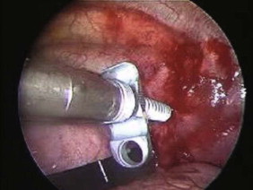
Screw Insertion
Before the cannulated screw is inserted into the adjacent vertebral body, the K-wire is impacted ( Figs. 31-8 and 31-9 ). The insertion point is 1.5 cm from the posterior border of the vertebral body and 10 mm away from the end plate, and the insertion depth is about 20 mm. The correct point should be confirmed with fluoroscopic guidance; it is also important to confirm the perpendicular position of the patient to the beam. The polyaxial posterior screw is placed over the K-wire ( Figs. 31-10 and 31-11 ). The direction of the polyaxial clamp can be controlled by the handle. The clamp must be oriented such that the hole for the anterior stabilization screw comes to lie anteriorly. After the first turns of the screw into the vertebral body, the K-wire must be removed to avoid the risk of tissue perforation by pushing the K-wire forward during screw insertion. After partial insertion of the polyaxial screws, the K-wire must be removed.


Diskectomy
After the screw is inserted into the adjacent vertebral body, the disks are removed. The disk is shrunken with a monopolar coagulator and removed with a curette ( Fig. 31-12 ). For the effective removal of the disk, the rib head should be drilled away. The proximal 2 cm of the rib is removed using a high-speed drill to expose the lateral surface of the pedicle and neural foramen.

Corpectomy
After the disk is removed, the corpectomy margin is prepared with a monopolar coagulator ( Fig. 31-13 ). When the anterior margin is coagulated, the coagulation point should be 10 mm away from the great vessels ( Fig. 31-14 ). After the parietal pleura is coagulated, the extent of the planned vertebrectomy is defined with an osteotome. The tumor mass is removed piece by piece with a curette and pituitary forceps ( Fig. 31-15 ). For the complete decompression of the spinal cord, the pedicle should be removed. The lower border of the pedicle should first be identified with a blunt hook. The base of the pedicle is then resected in a cranial direction with a Kerrison rongeur, and the thecal sac can be identified from the lateral direction. The decompression is continued until the ventral surface of the dura is visualized ( Fig. 31-16 ). The posterior longitudinal ligament can be removed with the Kerrison rongeur to expose the dura. Bone bleeding is controlled with bone wax, and epidural hemostasis is achieved with Gelfoam and bipolar cautery.


Related posts:
 Approaches to the Craniocervical Junction: Posterior and Lateral Approaches
C1–C2 Trauma Injuries and Stabilization Techniques
Cervical Disk Arthroplasty Techniques
Anterior and Posterior Cervicothoracic Junction Stabilization Techniques
Surgical Decompression and Stabilization for Lumbar Lesions: Osteomyelitis and Tumors
Surgical Approach to Posttraumatic Thoracic Kyphosis
Approaches to the Craniocervical Junction: Posterior and Lateral Approaches
C1–C2 Trauma Injuries and Stabilization Techniques
Cervical Disk Arthroplasty Techniques
Anterior and Posterior Cervicothoracic Junction Stabilization Techniques
Surgical Decompression and Stabilization for Lumbar Lesions: Osteomyelitis and Tumors
Surgical Approach to Posttraumatic Thoracic Kyphosis
Stay updated, free articles. Join our Telegram channel

Full access? Get Clinical Tree


