Fig. 11.1
DTRAX Cervical Cage in three configurations
The DTRAX Cervical Cage is compatible with a variety of retractors and instrument sets, including DTRAX Spinal System. Figure 11.2 shows many of the key instruments comprising the DTRAX Spinal System; these include:
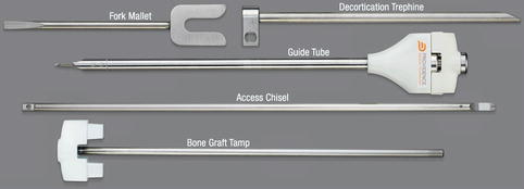
Fig. 11.2
Key instrumentation components of the DTRAX spinal system
Fork Mallet
Decortication Trephine
Guide Tube
Access Chisel
Bone Graft Tamp
Indications for Use
This surgical technique is indicated for use in skeletally mature patients with cervical spondylosis (C3–C7) and accompanying radicular symptoms at a single level. The level of pathology is confirmed by detailed patient history and radiographic studies. Patients should have received at least 6 weeks of non-operative treatment prior to treatment with the device. The devices are intended to be used with autogenous bone graft and supplemental fixation, such as a bone screw or an anterior plating system.
Contraindications
Contraindications include the following:
Cervical spondylosis, cervical myelopathy, cervical kyphosis; infection; allergy to titanium; pregnancy; Paget’s disease; renal osteodystrophy; cancer of the spine; obesity; rheumatoid arthritis; bone absorption, osteopenia, poor bone quality, and/or osteoporosis .
Surgical Technique
Operating Room and Patient Preparation
Confirm the operating table and patient head support are both radiolucent so that these two objects will not interfere with fluoroscopy. Check that there is adequate space at the head of the table to place and position C-Arm(s) and that there is sufficient spacing away from the sterile field. After routine intubation, place the patient in a prone position with patient’s head on a foam donut with a slight flexion of the head. Use tape to pull the patient’s shoulders inferiorly and secure in place (Fig. 11.3).
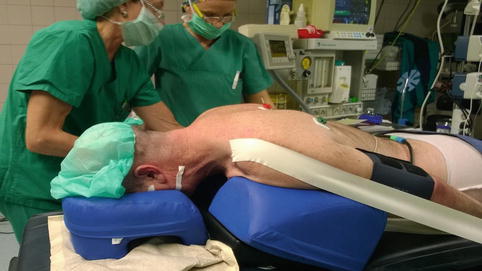
Fig. 11.3
Patient preparation involves prone positioning, head support and pull-down of shoulders
C-Arm Preparation
Set up the C-Arm at the side of the table in AP with the arm fully retracted. Find a clear AP view. Advance the C-Arm while rotating the detector back to find the lateral view. A fully retracted C-Arm allows for finding the lateral view by advancing the arm of C-Arm instead of moving the whole machine. Returning to the AP position only requires rotating the detector forward while fully retracting the C-Arm. This C-Arm set up allows clear imaging to be retained while rapidly switching between views.
The use of two C-Arms is recommended for ease of imaging which can improve safety and significantly reduce the time length of the procedure. If a second C-Arm is used, leave the first C-Arm in the lateral position. Rotate the first C-Arm 20–30° so that the arm is under the patient’s shoulders. This provides room for the second C-Arm under the patient’s neck. Place the second C-Arm at the head of the table and with the arm fully advanced to find the AP view. Finding the AP view with the arm of the second C-Arm fully advanced allows the arm portion to be retracted during the procedure to create working space for tools, then fully advanced to quickly restore AP imaging. On the second C-Arm add approximately 20° caudal/cranial inclination; this adjustment, along with the flexion of the head, allows an en face or near en face view of the target facet joint (Fig. 11.4).
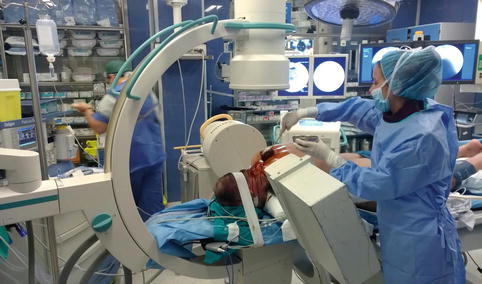
Fig. 11.4
The use of two C-arms for lateral and AP views concurrently is recommended
Skin Markings and Sterile Field
Images clearly demonstrating facet joint anatomy are essential for proper preoperative skin markings. Use fluoroscopic guidance to identify surgical border and level to be treated. Identify and mark the medial and lateral borders of the facets using AP view on fluoroscopy, a slender, straight metallic instrument (e.g. K-wire or Steinman pin), and surgical pen (Fig. 11.5). Identify and mark the operative level using the same method (Fig. 11.6). Prepare and drape the patient’s posterior neck in a routine sterile fashion. It is recommended the C-Arm(s) remain in place during this portion so that the radiological markers are not lost. Open the kits containing the surgical instruments and implants. Arrange the instruments in the order in which they will be used (Fig. 11.7).
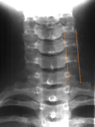
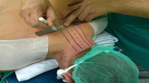
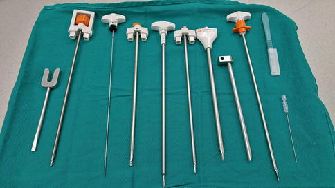
Fig. 11.5
The medial and lateral borders of the facets are identified using AP view
Fig. 11.6
The operative level is identified and marked on the patient
Fig. 11.7
Typical arrangement of instruments for surgery
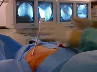
Establish Trajectory and Access the Facet Joint
Use a spinal needle to confirm the trajectory under fluoroscopic guidance (Fig. 11.8a). Due to the acute angle of the facet joint the trajectory often results in the entry point being located approximately two finger widths below the target level. Reinsert or reposition the spinal needle as needed until the correct trajectory is confirmed. The correct trajectory will match the angle of the facet joint (Fig. 11.8b). Repeat this process for the contralateral side. If desired the needles may be used to administer local anesthesia and/or epinephrine for pain or bleeding control. Remove the first spinal needle while leaving the contralateral needle in place to provide a guidance reference.
Fig. 11.8
(a) The spinal needle confirms trajectory under fluoroscopic guidance. (b) The spinal needle is positioned to match the angle of the facet joint
Make initial incision at the midline by the confirmed entry points and carry through the subcutaneous tissue and the fascia. Use a hemostat to spread the fascia and paraspinal muscles laterally. Direct visualization of the surgical site with the naked eye can be achieved. Under AP fluoroscopic guidance, advance the Access Chisel through incision with the chisel blade in the vertical position until bone is reached (Fig. 11.9a). Rotate the Access Chisel 90°. Using control in AP and lateral fluoroscopy, find the superior portion of the facet joint, lower Access Chisel tip to find and cut the capsule of the joint, and advance the Access Chisel into facet joint using hand pressure and/or light malleting (Figs. 11.9b, c).
Fig. 11.9
(a) The Access Chisel is advanced until bone is reached. (b) The Access Chisel tip is lowered to find and cut the capsule of the joint. (c) The Access Chisel is advanced into facet joint
Decorticate the Lateral Masses and Establish Working Channel
Advance the Decortication Trephine over the Access Chisel until the distal tip contacts bone (Fig. 11.10a, b). Decorticate each lateral mass with 10° rotations of the Decortication Trephine . This action will strip the muscle subperiosteally and create bleeding from the bone. Disengage and retract Decortication Trephine from the lateral mass before rotating to address the inferior lateral mass. Remove Decortication Trephine by retracting it while maintaining position of the Access Chisel. To establish the working channel, place the Guide Tube over the Access Chisel. Use the Fork Mallet to advance the Guide Tube into the facet joint. Verify Guide Tube placement on both lateral and AP views. Proper and final Guide Tube depth is achieved when the markers are at the entry point of the facet joint on lateral view and the Guide Tube is centered between the medial and lateral borders of the facet joint on AP view (Fig. 11.11). Remove the Access Chisel while maintaining position of the Guide Tube in the facet joint.
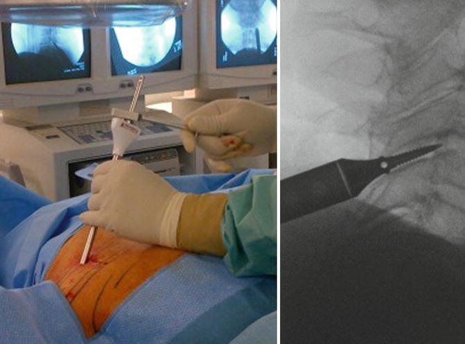
Fig. 11.10
(a) Detailed view of the Decortication Trephine, which is advanced over the Access Chisel. (b) The Decortication Trephine is advanced over the Access Chisel until the distal tip contacts bone
Fig. 11.11
The Guide Tube is advanced into the facet joint using the Fork Mallet
Decorticate the Facet Joint
Insert the Decortication Rasp through the Guide Tube and advance using the Fork Mallet until the upper handle of the Decortication Rasp locks with the handle of the Guide Tube (Fig. 11.12). Retract the Decortication Rasp by inserting the screwdriver head of the Fork Mallet into the space between handles and turning. This allows controlled removal of the Decortication Rasp while maintaining the position of the Guide Tube in the facet joint. Turn the Decortication Rasp 180° and advance into the joint. Retract as before using the screwdriver head of the Fork Mallet. Remove the Decortication Rasp and clean off bone and cartilage. Reintroduce the Decortication Rasp and repeat these steps to further decorticate, achieve bleeding of the bone, and remove joint material. Remove the Decortication Rasp one last time while maintaining position of the Guide Tube in the facet joint.