Chapter 142 Upper Cervical Screw Fixation Techniques
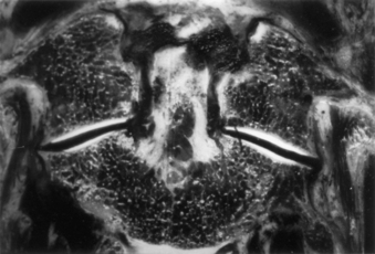
Internal fixation is often used to provide immediate stabilization to protect the vital neural and vascular elements rendered vulnerable by instability produced by trauma, disease processes such as rheumatoid arthritis or neoplasms, and surgical procedures such as transoral odontoidectomy. Immediate stabilization is especially important in the highly mobile cervical spine. The occipitocervical junction and atlantoaxial complex constitute a transitional region connecting the rest of the spinal column to the cranium. The vertebrae and joints in this area differ from the vertebrae and joints in the subaxial spine, with special modifications to allow unique degrees of motion. Possibly the most important of these are at the C1-2 complex, where the flat lateral articulations, absence of an intervertebral disc, and lax ligaments permit appreciable rotation at C1-2 (about 50% of total head rotation) (Fig. 142-1).1 This motion is safely tolerated because the spinal canal is more generous, the instantaneous axis of rotation is located close to the spinal cord (minimizing distortion of that structure), and the vertebral arteries loop laterally (allowing for at least one to remain patent, even at the extremes of rotation). Potentially catastrophic translational movements, which would crush the spinal cord, are prevented by the very strong transverse component of the cruciate ligament (usually 8 to 10 mm in diameter in adults) that contains the odontoid process of the axis in the ventral compartment of the atlas. Disruption of this ligament, with or without bursting of the ring of C1 (Jefferson fracture), or disruption of the odontoid process results in gross instability. The remaining ligamentous structures, if intact, may provide some support, but they are too weak intrinsically to protect the spinal cord from even relatively minor trauma.
General Considerations
Protection of the neural elements when instability exists is paramount. Before surgery, the patient must be properly immobilized. Depending on the degree of instability, immobilization may be achieved with a rigid cervical collar, or it may require skeletal traction, a halo vest, or a Minerva jacket. Ongoing spinal canal compromise, if present, should be corrected before fusion is attempted by restoring alignment with cervical traction via cranial tongs or by surgical removal of intraspinal masses. After the nature of the pathologic condition has been fully investigated and restoration of physiologic relationships between neural elements and the spinal column has been managed, surgical stabilization can be planned. The overall medical condition of the patient should be optimized, and other injuries should be evaluated and treated as appropriate.
Ventral Approaches
Indications
Ventral techniques are primarily indicated for direct screw fixation of odontoid process fractures. C2-3 ventral fusion and plating may be used for hangman’s fracture.2 It is no different from ventral cervical fusion and plating at lower levels other than the difficulty associated with the angle of approach to C2. The retractor system used for odontoid screw fixation sometimes may be useful in this regard.
Odontoid process fractures were classified by Anderson and D’Alonzo3 as types I, II, and III. Type I fractures involve the apical part of the odontoid process, are quite rare, and are usually believed to be stable. However, one report suggested otherwise,4 and dynamic imaging should be used to assess stability. Type II fractures involve the neck of the odontoid process and are the most common. Type III fractures extend into the body of C2 and generally heal well with immobilization. However, in a comprehensive review of fractures of the C2 vertebral body, Benzel et al.5 noted that the type III fracture described by Anderson and D’Alonzo3 is not an odontoid fracture at all. Benzel et al.5 proposed a classification of C2 body fractures that is more comprehensive and more meaningful in regard to mechanisms of injury.
Debate continues regarding the optimal treatment of type II fractures. Reported nonunion rates range from 7%6 to 100%.7–12 A meta-analysis13 found that halo vest immobilization produced a fusion rate of 65%. The variable success of immobilization led some authors to try to define parameters that would predict failure with external immobilization. Extent of dislocation (67% nonunion if dislocation is >6 mm,14 88% nonunion with dislocation >4 mm15), patient age (higher failure rate in older patients15,16), and direction of subluxation (higher failure rate with dorsal subluxation16) all have been suggested as predictors, as has a comminuted fragment of bone at the base of the odontoid process (type IIA).17 Although these studies fail to agree on many points, they do emphasize the nature of the problem.
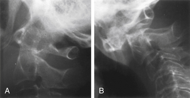
Degree and direction of offset may be misleading indicators because they have been identified based on single rather than dynamic radiographs (Fig. 142-2). However, age seems to be an important valid indicator of the propensity for nonunion. In a randomized controlled prospective study, Lennarson et al.18 found the nonunion rate was 21 times greater in patients older than 50 years who were treated with halo immobilization than in younger patients. This study was a key factor leading to a recommendation for surgery in the guidelines for management of acute cervical spine and spinal cord injuries published by the Joint Section of Disorders of the Spine and Peripheral Nerves of the American Association of Neurological Surgeons and Congress of Neurological Surgeons.19
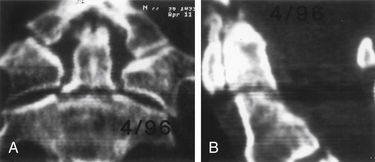
Because nonoperative treatment of type II odontoid fractures has a high nonunion rate (Fig. 142-3), several alternative methods of surgical fixation have been developed. The traditional operative technique for type II odontoid process fractures has been C1-2 dorsal wiring and arthrodesis. A relatively high fusion rate is associated with this technique; however, rigid postoperative bracing for at least 3 months is necessary, and successful fusion results in a significant reduction in head rotation. The dorsal approach also has an associated traumatic effect on cervical muscles. All these disadvantages can be obviated by using direct ventral odontoid screw fixation techniques.
Direct Ventral Odontoid Screw Fixation
Direct screw fixation of the odontoid process was first described in 1980 in the Japanese literature by Nakanishi,20 who began using this technique in 1978. This description was followed in 1981 and in 1982 by publications from Böhler,21,22 who reported his experience dating back to 1968. Although others23–26 described their experiences with various approaches to achieve direct odontoid screw fixation, the procedure was not widely accepted. With the development of specialized instrumentation facilitating accurate screw placement and minimal trauma to the patient,27–29 the procedure has gained in popularity. The technique has the advantages of (1) decreased postoperative pain resulting from lack of extensive muscle dissection, (2) avoidance of bone graft harvest, and (3) maintenance of normal anatomy and rotation at the C1-2 joint.30 Many patients require no postoperative immobilization.
Direct ventral odontoid screw fixation can be used as the primary approach to treat acute type II fractures. Patients with type II dens fractures with concomitant C1 ring fracture may also be candidates for odontoid screw fixation. However, assessment of transverse ligament integrity by MRI preoperatively31 and by flexion fluoroscopy postoperatively is essential. If the latter shows continued C1-2 instability, either a ventral or a dorsal C1-2 fusion is necessary. The direct screw fixation technique may also be used in some patients with chronic nonunion of type II odontoid fractures. Candidates should have a relatively small gap between the odontoid process and the C2 body and a reasonably sized odontoid fragment that has not autofused to C1 and does not have sclerosis of the surface opposing the body of C2. Chronic malunions that do not meet these criteria rarely fuse and ultimately fracture the hardware and become unstable. The chance of successful bony union in one small series of such patients with fractures of more than 18 months of age was only 25%32; this sharply contrasts with an 88% fusion rate for type II and high type III fractures of less than 6 months of age.32 For this reason, we generally recommend posterior C1-2 fusion for chronically nonunited fractures. Unstable type III odontoid fractures that do not extend too far into the body of C2 are also potential candidates for direct screw fixation.
Contraindications
Absolute contraindications include comminuted fractures of the C2 body and transverse ligament disruption, as defined by MRI or suggested by a C1 lateral mass fracture with extensive lateral displacement (>7 mm total on anteroposterior radiographs)33; pathologic fractures; and nonunions of fractures that occurred more than 6 to 8 months previously that do not meet the aforementioned criteria. A relative contraindication is severe osteoporosis. In addition, an oblique fracture of the odontoid process, angled caudally and ventrally so that it is parallel to the planned screw trajectory, may not be as suitable for ventral screw fixation because the odontoid process may slide down the fracture plane as the screw is tightened. Although they account for only 16% of the cases in one published series,32 these anterior oblique fractures had a significantly higher failure rate. By starting fixation in a position of slight retrolisthesis and augmenting the construct with a rigid cervical collar to restrict flexion, successful fusion has been achieved in patients with anterior oblique fractures.
Patient Positioning
For odontoid or ventral C1-2 screw placement, biplanar fluoroscopy is necessary. The anteroposterior view is obtained transorally. A wine bottle cork, notched for the teeth or gums, is an ideal radiolucent mouth prop. A single fluoroscope, swung back and forth frequently from the lateral to the anteroposterior position, can be used if necessary. A triangular space for one side of the C-arm can be walled off with drapes and IV poles to facilitate frequent positioning and minimize the need to redrape the C-arm. It is much easier, however, to use a second C-arm fluoroscope if one is available. One C-arm unit is placed laterally with the arc horizontally or up to 45 degrees above the horizon. The other can be brought in at a 45-degree angle from the head of the table and positioned for the transoral view (Fig. 142-4).

Operative Technique
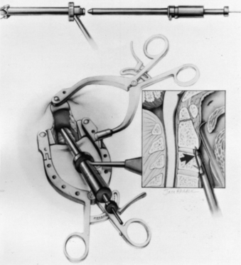
Several screw systems have been used, but all ventral odontoid fixations begin with the same exposure. The initial approach to the spine is the same as for an anterior cervical discectomy. The spine is approached at about the C5 level through a unilateral natural skin crease incision (Fig. 142-5). We use a local injection with epinephrine (1:200,000) to minimize skin bleeding and complete hemostasis with bipolar cautery. The platysma muscle is elevated and divided with monopolar cautery. The sternocleidomastoid muscle fascia is opened along the medial side of the muscle with sharp dissection. Blunt dissection opens the deeper tissue planes medial to the carotid sheath and lateral to the trachea and esophagus to expose the prevertebral space. Dividing the longus colli fascia and the anterior longitudinal ligament in the midline with electrocautery allows the bellies of the longus colli muscle to be elevated bilaterally over approximately 1.5 vertebral segments. Sharp-bladed Caspar retractor blades are set in place below the muscle and attached to the Caspar retractor.
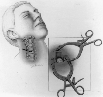
FIGURE 142-5 Skin incision in a natural skin crease at about the C5 level. Inset shows retractor in place.
The loose areolar tissue in the prevertebral space ventral to the longus colli muscles is easily opened with a Kittner or “peanut” dissector held in a curved tonsil clamp. It is swept from side to side while advancing up to the C1-2 level (monitored with lateral fluoroscopy). The Apfelbaum system (Aesculap Instrument Corporation, Center Valley, PA) has an angled retractor blade that reaches into this space under the mandible and holds open the working tunnel. It attaches to one side of the previously placed modified Caspar retractors (see Fig. 142-5). Other systems use different retractors, such as a curved hand-held retractor (Synthes) or small metal hook-shaped hand-held Hohmann retractors that lock over the shoulders of C2 bilaterally alongside the dens, as initially described by Böhler.21 The key to the retraction is to create a working tunnel up to the caudal edge of C2, without having any device caudally in the wound that restricts the low trajectory needed for proper screw placement.
At this point, the various instrument systems use different approaches for placing the screws. The Apfelbaum system consists of an outer guide tube with spikes that anchor it to C3 and that can be used to optimize spinal alignment. An inner guide tube, within the outer tube, guides the drilling. After the pilot hole is drilled, the inner guide is removed, the hole is tapped, and the screws are placed through the outer guide tube. First, under biplanar fluoroscopic control, an entry site on the ventral caudal edge of C2 is selected, and a K-wire is impacted into C2 (Fig. 142-6A). If one screw is to be placed, a midline location is chosen. If two are to be placed, a paramedian location is selected 2 to 3 mm from the midline. Care and patience in selecting the entry site and setting the K-wire are rewarded by the remainder of the procedure being expedited. When the K-wire is set, a 7-mm hollow drill is placed over the K-wire and is rotated by hand to create a shallow trough in the face of C3 and in the C2-3 anulus (Fig. 142-6B–D).
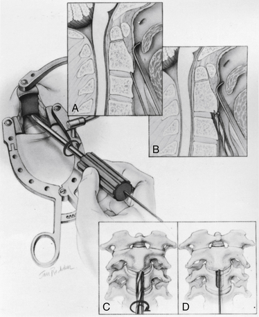
FIGURE 142-6 A, A guiding K-wire in place. B–D, Hollow hand drill creates a trough in the face of C3 and C2-3 anulus.
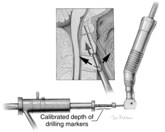
No bone is removed from C2. The two guide tubes are mated together, passed over the K-wire, and walked up the ventral face of the spinal column until the spikes on the outer tube are over the body of C3. The inner guide tube is advanced in the trough to the ventral caudal edge of C2 (Fig. 142-7), and the K-wire is removed. Having the guide tube at the entry site prevents the drill from skipping off the edge of the bone and walking up the ventral face of C2. With the guide tube system firmly engaged in C3, the surgeon can optimize the C2 alignment on the fluoroscopic images by either pushing C2 and C3 dorsally relative to the odontoid-C1 complex or pulling C2 and C3 ventrally. In the case of a retrolisthesed odontoid process, this realignment can be performed while gradually extending the patient’s head and removing the supporting towels beneath it to obtain an ideal working trajectory.
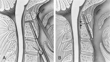
A pilot hole is drilled from the ventral caudal edge of C2 to the apex of the odontoid process, advancing the drill slowly under biplanar fluoroscopic control (Fig. 142-8). The dense cortical shell of the odontoid must be pierced to engage the screw properly and avoid splitting. Because the odontoid process is firmly held in position by its periosteum and attached supporting ligaments, it is not displaced as the drill enters from the soft cancellous fracture site. The angle of drilling is such that the drill can penetrate a substantial distance beyond the apex of the odontoid process into the apical ligaments without threatening the dural or neural structures. However, if a more dorsal trajectory is needed, greater care must be taken not to penetrate too far into the spinal canal; this is controlled by visualizing the progress of the drill on the fluoroscope.
The drill is withdrawn, and the inner guide tube is removed. A tap is placed through the outer guide tube, and the pilot hole is tapped. Threads are cut in the bone, allowing a more precise bone-screw junction that may reduce bone absorption around the screw caused by pressure necrosis if a self-tapping screw is used. The tap is removed, and a screw is placed through the guide tube (Fig. 142-9). A screw that is a few millimeters shorter than the measured drill depth may be chosen to allow for reduction at the fracture site, but it is important that the screw fully engages the apical cortex. Extending the screw a few millimeters beyond the cortex into the apical ligaments is safe and preferable to having one too short because the latter may (and has in our experience) back out. To achieve some fracture reduction, a partially threaded screw (lag screw) is used to pull the odontoid back toward the body of C2.
Several alternative systems have been proposed that are often based on existing long bone screw fixation techniques. These systems use a K-wire to drill the pilot hole and pass a hollow overdrill over this, followed by a cannulated screw.24 Theoretically, after the K-wire is placed, it does not have to be removed so that precise reentry into the same trajectory is assured; however, a drawback of these systems is that they do not appear to have any provision for optimizing alignment with the drill guide, as described earlier, except by trying to do this by repositioning the head or placing additional instruments beside the drill and pushing on C1 or C2. K-wires are suboptimal drills because they lack the torsional rigidity of drill bits and can be deflected by irregular densities within the bone. To redirect them, one must remove the K-wire and select a new starting point.34 In addition, great care must be taken when drilling over the K-wire because the drill can bind to the K-wire and advance it into the spinal canal or cut the K-wire. This can also occur when placing the screw over the K-wire.


Stay updated, free articles. Join our Telegram channel

Full access? Get Clinical Tree


