Schematic of a differential amplifier used for EEG recording . The output of a differential amplifier is the difference between the two inputs
Discovery of EEG
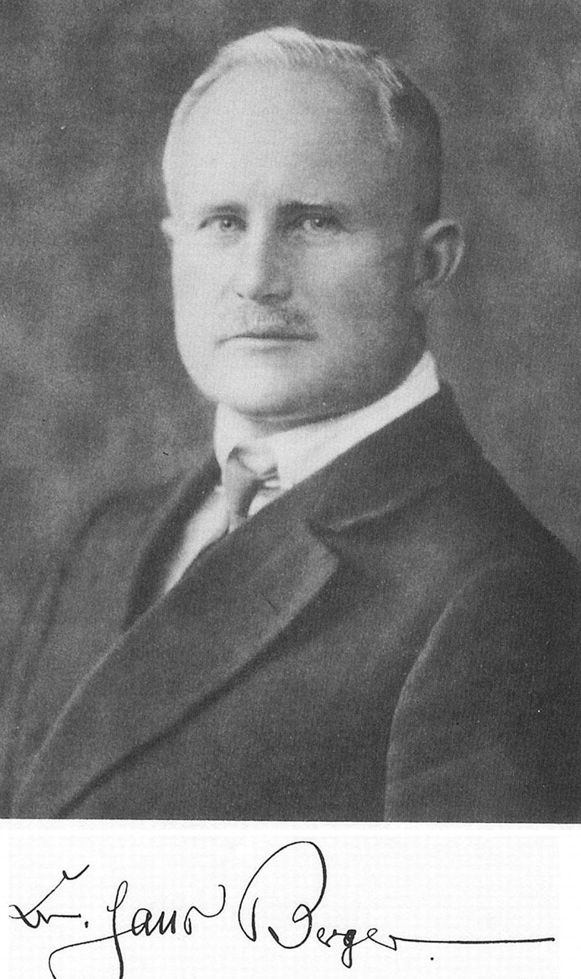
Hans Berger, a German psychiatrist, was the first to record EEG in humans (Fig. 10.2). Berger initially used a string galvanometer originally designed to record electrocardiograms. The initial recordings were from patients with open craniotomies, allowing the needle electrodes Berger used to be placed only a few millimeters from the surface of the brain. The first recording through an intact human skull was performed on Berger’s son. Berger’s first EEG paper titled “Electrokephalogram des Menschen” (“On the Electroencephalogram of Man”) was published in 1929 [1]. Berger’s reports were met with skepticism mainly due to the seemingly unexplainable slow oscillations (like alpha waves) having durations of about 100 ms. Scientists were expecting the generator of the signal to be single neuronal action potentials with durations of 1–2 ms. In 1935, prominent English physiologists, Adrian and Mathews, endorsed Berger’s work [2], and by 1936 there were six EEG laboratories in the United States [3].
Fig. 10.2
Hans Berger (1873–1941) recorded the first human electroencephalogram
By the 1950s, EEG was well established and the use of intracranial EEG known as electrocorticography (ECoG) was being pioneered by Wilder Penfield and Herbert Jasper to identify epileptogenic foci during epilepsy surgery [4]. ECoG is still used today to map the cortical surface for tumor resection and epilepsy surgery. Conventional EEG is also used in the OR for any procedure where there is a risk of cerebral ischemia and as a means of determining anesthetic depth.
Waveform Generators/Dipoles
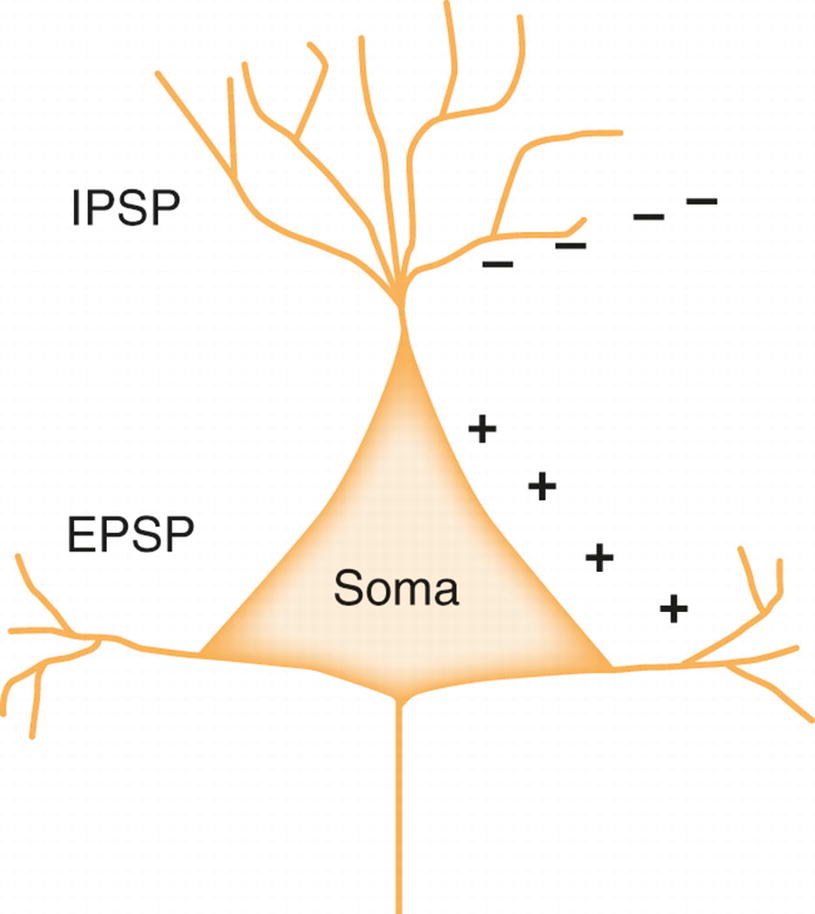
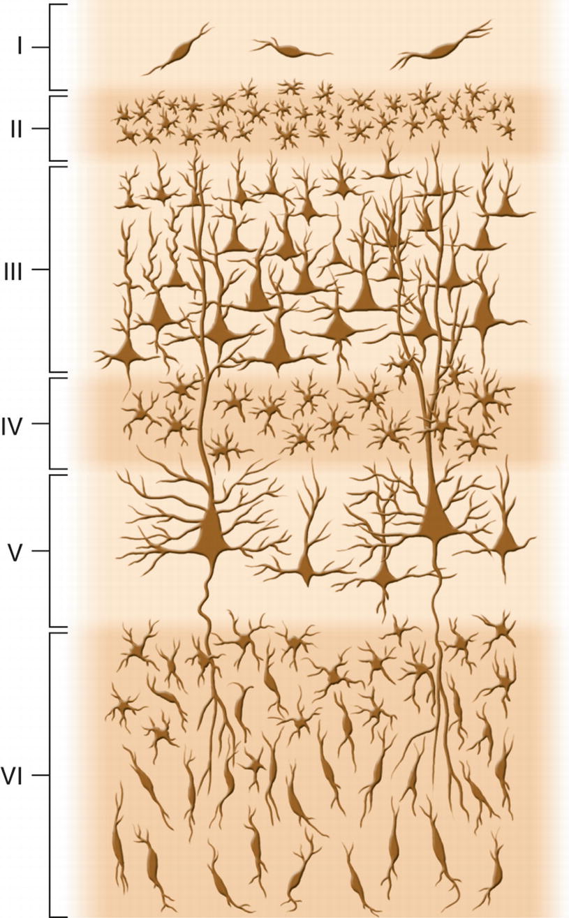
Postsynaptic potentials, having longer duration than the action potential, contribute to the EEG waveform [5]. As discussed in another chapter, postsynaptic potentials are either excitatory (EPSPs) or inhibitory (IPSPs) (Fig. 10.3). The EEG waveform is generated from the complex summation and integration of IPSPs and EPSPs arising from thousands of neighboring cortical neurons [6]. Pyramidal cells, mainly from layers III or V, are the major contributor of these synaptic potentials, which is owed to their spatial organization within the cortex (Fig. 10.4). Being linearly arranged, these neurons have an open electrical field and produce a dipole (discussed below). The ability to record EEG depends on the synchronization of the cortical neurons. This synchronization is achieved because of the inputs from subcortical structures such as the thalamus.
Fig. 10.3
Schematic of a neuron and the influences of postsynaptic potentials. EPSP excitatory postsynaptic potential , IPSP inhibitory postsynaptic potential
Fig. 10.4
Layers of the cerebral cortex
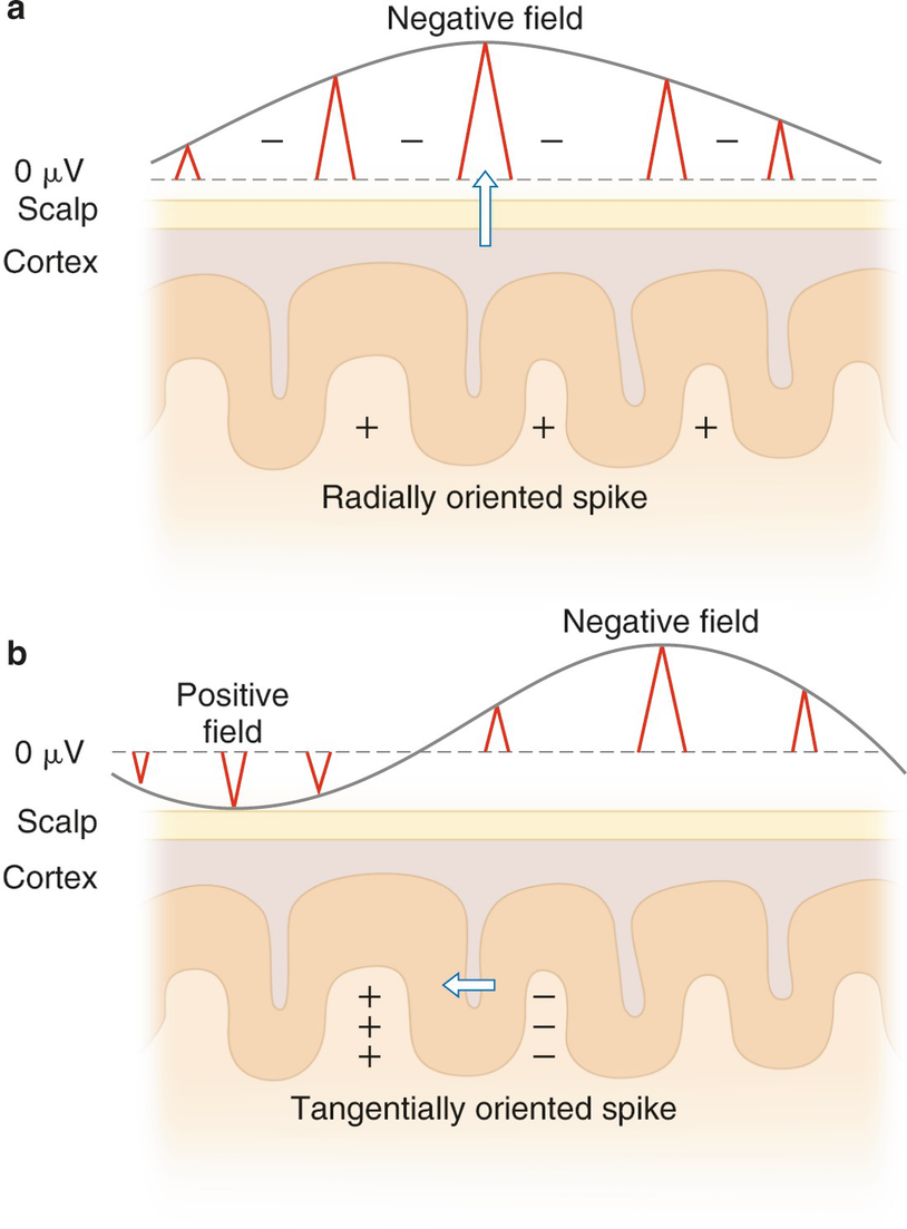
Neuronal potentials have a negative and a positive field called a dipole. When the discharge is generated at the top of the cortex, it creates a radially (vertically) oriented dipole with a maximum negativity just above the source with a positive field either deep within the hemisphere or in the opposite hemisphere, depending on the orientation of the neuronal field (Fig. 10.5, panel a). When the discharge is generated in a sulcus of the cortex, it creates tangentially (horizontally) oriented dipoles with the fields of maximum negativity and positivity being displayed in an anterior/posterior or medial/lateral orientation (Fig. 10.5, panel b).
Fig. 10.5
Schematic representation of dipoles in relationship to the scalp surface. Panel (a) depicts a radially oriented discharge arising from the crown of the cortex with a negative field above the source and a positive field within the cortex. Panel (b) depicts a tangentially oriented discharge arising from a sulcus with surface negative and positive fields posterior and anterior to the source
10–20 System and Electrode Nomenclature
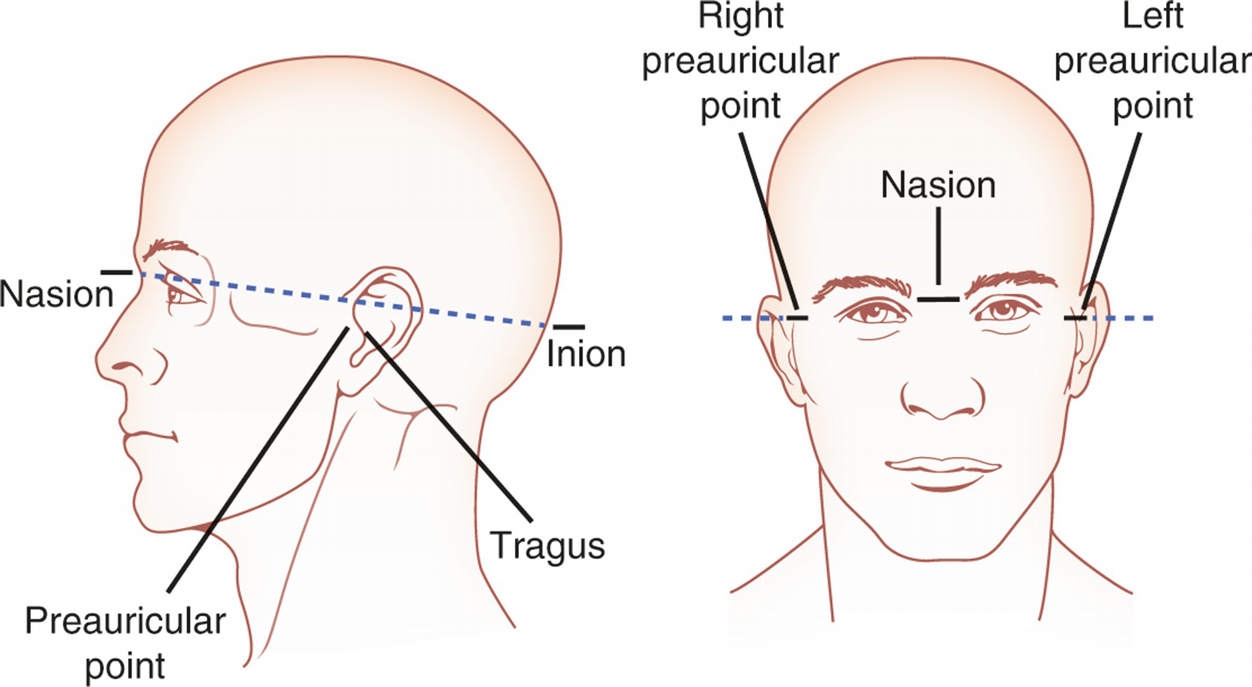
The International 10–20 System of electrode placement was developed in 1958 as the standard placement of scalp electrodes [7]. Anatomical landmarks on the skull are used as reference points for the measurement. The four anatomical landmarks are the nasion, the indentation between the forehead and the nose; the inion, the midline bump or ridge on the back of the skull; and the preauricular points, the indentations just above the cartilage (tragus) on the left and right ears (Fig. 10.6). Electrode designations act as binomial coordinates with the first coordinate of the designation indicating the anterior/posterior position and the second coordinate indicating the medial/lateral position. The anterior/posterior coordinates correlate with brain landmarks such as lobes or sulci. The most common designations used for intraoperative monitoring are shown in Table 10.1.
Fig. 10.6
Skull landmarks that are reference points for the International 10–20 System of electrode placement
Table 10.1
International 10–20 System electrodes most commonly used during intraoperative neurophysiological monitoring
A/P designation
Name
Description of location
Fp
Frontopolar
Over frontal pole of brain
F
Frontal
Over frontal lobe
T
Temporal
Over temporal lobe
C
Central
Along central sulcus
Cp
Central–parietal
Midway between C and P line
P
Parietal
Over parietal lobe
O
Occipital
Over occipital lobe
The medial/lateral electrode positioning has a numerical designation. By convention, electrodes to the right of midline are designated with even numbers and to the left with odd numbers. Electrodes on the midline are designated as “z” because they correspond to an imaginary “z line” that runs along the longitudinal fissure. The numbers increase further from midline.
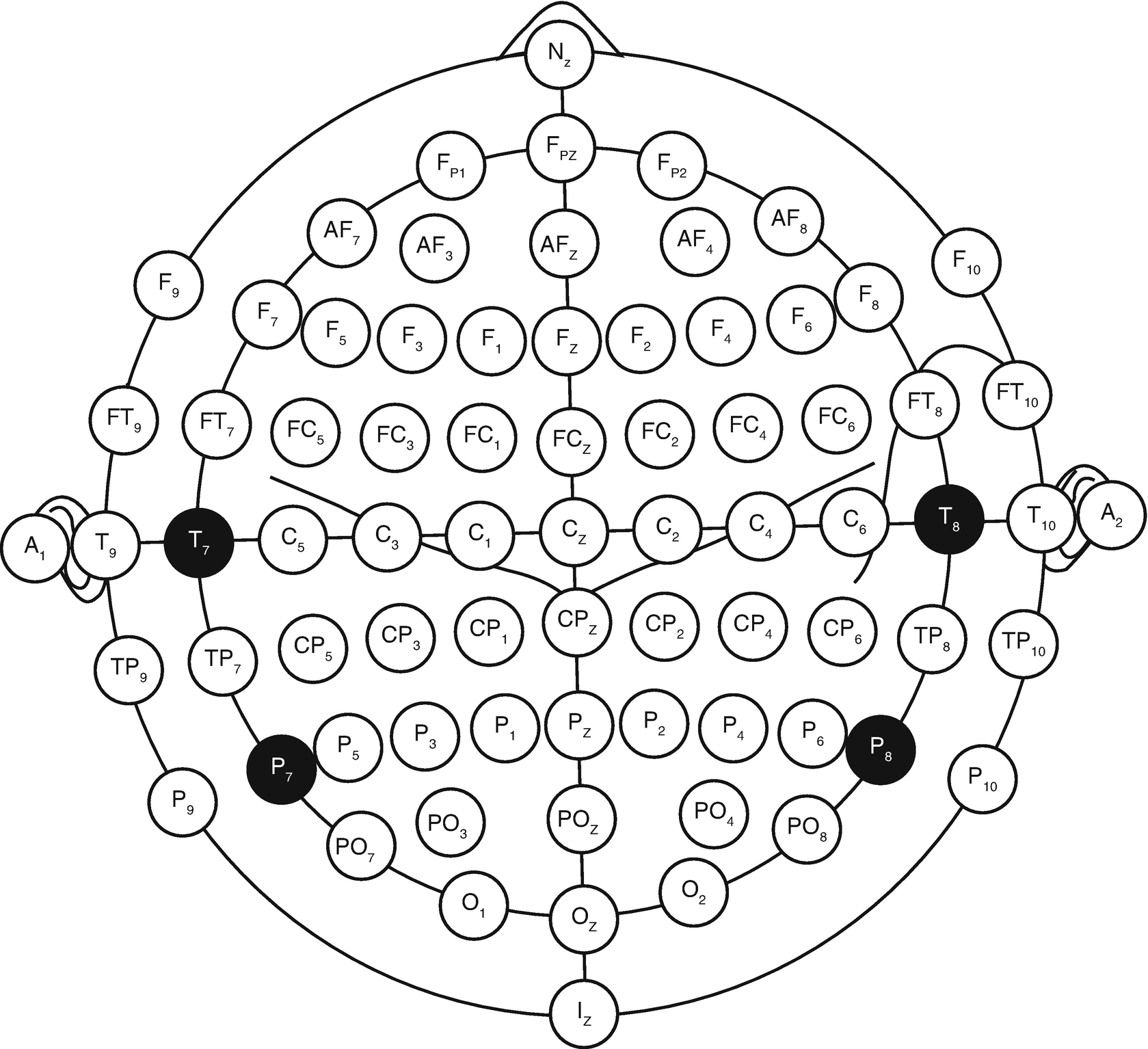
In 2006, the American Clinical Neurophysiology Society (ACNS) recommended electrode nomenclature using the 10–10 system (Fig. 10.7). T3 and T4 are designated at T7 and T8. T5 and T6 are designated as P7 and P8. The measurements to determine these electrode sites are exactly the same as the International 10–20 System [8].
Fig. 10.7
Nomenclature for the 10–10 system
Electrodes
Various electrode types can be attached to the scalp for the purposes of recording EEG. In a clinical setting, 4- to 10-mm metal disk or cup electrodes are most frequently used. These may be gold plated, silver, or silver–silver chloride. An electrolyte or conductive gel is placed between the electrode and the scalp to lower impedance and increase the quality of the signal. The electrode is secured with an adhesive such as collodion or paste. Desirable electrode impedances are under 5 kΩ. For intraoperative EEG, stainless steel subdermal needles are more commonly used. These can be quickly and safely inserted just under the scalp and provide excellent quality recordings. Electrode removal is likewise quick and clean! Corkscrew electrodes are similar to subdermal needles and are advantageous for cranial procedures due to the decreased ability to replace dislodged electrodes close to the sterile field.
Montages
A montage is a systematic and logical combination of multiple pairs of electrodes that are used for electrophysiological recording. An acceptable montage for EEG should compare activity from homologous electrodes between the two hemispheres. For intraoperative monitoring, there are two main types of recording montages: bipolar and referential. Bipolar montages compare active electrode sites adjacent to each other. An example of a bipolar montage used for EEG is the anteroposterior (AP) montage (Table 10.2).
Table 10.2
Anteroposterior (AP) bipolar montage for recording EEG
Left
Right
Fp1–F3
Fp2–F4
F3–C3
F4–C4
C3–P3
C4–P4
P3–O1
P4–O2
Fp1–F7
Fp2–F8
F7–T3
F8–T4
T3–T5
T4–T6
T5–O1
T6–O2
Only gold members can continue reading. Log In or Register to continue