Intraoperative images through the microscope of various stages of surgery for a mid-cervical IMSCT . (a) Placement of the spinal electrode used for recording D-waves. In this figure, the dura is open and retracted using stitches, seen here in black, revealing the vascularized spinal cord in the center of the image. The spinal electrode, seen here with two of three contacts visible, is gently guided by the surgeon into the epidural space inferior to the location of the lesion. (b) Stimulation of the spinal cord with a monopolar probe during dorsal column mapping. (c) Midline dorsal myelotomy via scalpel. (d) Tumor retraction and tumor forceps. (e) Cavitron ultrasonic aspirator (CUSA)
Stabilize the wire exiting the spinal electrode using the surgical drape clamped around the wire with a hemostat. Be sure to check that the delicate wire of the spinal electrode has not been clamped directly as this may cause interruption of the wire and/or its insulation, resulting in poor recordings.
Encourage the surgeon to suture around the epidural electrode as it exits the dura and affix it to the surrounding tissue.
Take note of the position and location of the electrode even if with a photograph. This can be aided by putting a fiducial mark on the epidural electrode as it exits the epidural space. Spinal electrodes often have fiducial marks of their own.
We encourage the neurophysiologist to attempt D-waves promptly after the placement and plug-in of the spinal electrodes. This gives time to troubleshoot the contact and placement of the spinal electrode(s) and optimize the stimulation parameters.
Once an optimized D-wave has been obtained and reported, spinal cord mapping may follow. The mechanics of the mapping depend on the method of choice (see below), but they include handoff of a sterile electrode required to stimulate directly or record directly from the spinal cord. Often, access into the spinal cord is at the posterior median sulcus which separates the left and right gracile fasciculi. Anatomically, the posterior median sulcus is at the midpoint between the dorsal root entry zones located at the lateral edges of a normal spinal cord. The visually estimated anatomical midline is compared with what is determined neurophysiologically to better approximate the location of this sulcus.
The spinal cord is opened by posterior midline myelotomy down the posterior median sulcus. This may be initiated directly by scalpel or by coagulation of dorsal midline veins and the superficial and medial aspect of the penetrating/diving fissure. The myelotomy is extended either with a scalpel or by splaying the cord via the outward pressure from the opening of closed micro forceps or the tips of the bipolar electrocautery device, with or without accompanying incising. Once the myelotomy is complete, some surgeons prefer to retract the dorsal columns either manually or with small sutures (such as pial traction sutures). Somatosensory evoked potentials (SSEPs , see below) are the focus of the IONM during these stages of the surgery. SSEP signal changes secondary to retraction forces applied on the dorsal columns indicate adjustments to retraction and/or the myelotomy are warranted. The surgeon should be encouraged to relax the tension on the tissue by either directly reducing retraction or indirectly by extending the myelotomy which allows the dorsal columns to open more freely.
Following the opening of the spinal cord, other types of mapping may ensue including localizing and even mapping the contents of the descending motor tracts through direct spinal cord stimulation. Selective or continuous mapping such as this may be incorporated throughout the resection.
Work on the tumor begins. A tissue specimen for biopsy is obtained using tumor forceps since the pathological identification of the tumor type is integral to the development of the surgical strategy and resection objectives. If there is a cystic component of the lesion, this may aid in identifying the leading and trailing ends of the tumor and help establish the resection plane. A cystic component of the tumor may make it difficult to obtain D-waves. While portions of a tumor that are clear and distinct from normal tissue may be removed by direct excision, tumors are typically debulked in an inside-out fashion. This is accomplished with the use of tumor forceps, electrocautery, or with a Cavitron Ultrasonic Surgical Aspirator (CUSA) . The CUSA uses high-frequency sound waves to morselize the tumor tissue, while preserving healthy tissue. These mobilized tumor fragments are suspended by irrigation fluids and aspirated away through the CUSA.
Working the marginal edges of the tumor and the tumor capsule from the surrounding nervous tissue is a critical stage of the surgery. Transcranial motor evoked potential (TcMEP) and D-wave monitoring is the focus of the IONM at this stage of the surgery. Tumor traction is often applied using the force generated by long-wise sweeps of the suction. Gentle counter traction on the spinal cord accompanied by isolation, division and electrocautery of adhesions and blood vessels are keys to successful excision.
At the completion of the tumor work, the dura is sutured closed. The surgeon will often request a Valsalva maneuver after the dura is closed to verify the integrity of the closure by looking for cerebrospinal fluid leaks during the period of higher intraspinal pressure temporarily created by the Valsalva. The epidural electrode(s) is/are likely to be removed at this point. Monitoring of D-waves should continue until the electrode(s) is/are removed. SSEP and TcMEP monitoring should continue until skin closure [7].
IONM in IMSCT Surgery
There are a number of published studies that represent the important contribution that spinal cord IONM and spinal cord mapping make to the surgical treatment of IMSCTs [7–20]. The monitoring modalities of SSEP and TcMEP, the most common IONM approaches during IMSCT surgery, and electromyography (EMG), a less commonly incorporated modality in IMSCT surgery, have been addressed in detail in other sections of this text. Therefore, the focus here will be on the addition of D-wave recording and on the methods of spinal cord mapping focusing on the dorsal columns and the corticospinal tracts (CSTs).
For IMSCT surgery, IONM including SSEP and TcMEP for monitoring spinal cord function should commence early. Patients with IMSCTs can be challenging neurophysiologically since they often have clinical or subclinical neurologic compromise. Pre-positioning baselines should be part of the IONM strategy for each of these cases. Post-position baselines without pre-position references introduce questions about the reason behind any incomplete or absent IONM data after positioning. Pre-position baselines also permit the surgical neurophysiologist the opportunity to evaluate and discuss the recordings and implement plausible adjustments to the IONM strategy to try to overcome deficiencies in data should they exist. Integrally, the surgical neurophysiologist must provide a thorough and detailed description of the pre- and post-positioning IONM recordings, as they should do throughout the procedure.
Somatosensory Evoked Potentials
For an in-depth view of SSEPs, I recommend the reader review Chap. 6 and the Association guidelines [21–23]. An SSEP is the bioelectric activity that originates from the nerves, tracts, and synapses along the ascending dorsal column-medial lemniscal (DCML) pathway . This pathway starts with the axons of dorsal root ganglia neurons that have terminal ends in the periphery. These axons, that carry fine touch, vibration, and proprioceptive information from sensory organs in the skin and from muscle spindles, course up the limb and into the lumbar plexus and lumbosacral plexus for axons of the lower limbs and the brachial plexus for axons of the upper limbs. They traverse the lateral neural foramen and pass into the spinal canal, transitioning from the peripheral to the central nervous systems. Each axon courses superiorly before approaching the spinal cord via the dorsal rootlets. Caudocranially, there is decreasing distance between the spinal level at which each axon enters the spinal column and the level at which it penetrates the spinal cord. Axons of the lower extremity course up the cauda equina, a distribution of nerve roots in the spinal canal ensheathed in the thecal sac, and enter the spinal cord at or just above the conus medullaris around spinal level L1.
After penetrating the spinal cord, the axons enter the posterior tracts, also known as the dorsal columns, and ascend the spinal cord toward the brainstem in distinct, somatotopically arranged, parallel tracts. The axons of the lower extremity course in the gracile fasciculi which bookend the posterior median sulcus. As you move up the spinal cord, axons from the trunk and then from the upper extremity systematically and successively join the dorsal columns laterally. In the cervical spine, the more lateral tracts, which are composed predominantly of the axons of the upper extremity, are the cuneate fasciculi.
In the direct, ascending pathway these axons make their first synapse in the gracile and cuneate dorsal column nuclei of the medulla. Axon collaterals also synapse in the spinal cord, participating in intraspinal neural circuits such as reflex arcs. The gracile and cuneate nuclei are independent regions of the medulla and maintain the separation of these parallel afferent pathways. Axonal projections from neurons in the gracile and cuneate nuclei decussate the brainstem in the internal arcuate of the medulla before ascending in the medial lemniscus toward the thalamus. Of note, a small percentage of patients have a non-decussating sensory pathway.
The ventral posterior nucleus of the thalamus is where the second synapse in the direct DCML pathway is found. The thalamus serves as a processing and relay center, and the pathway continues to the cortex from there. Thalamocortical projections make their way through the posterior limb of the internal capsule until they synapse on cortical pyramidal cells located primarily in the postcentral gyrus of the parietal lobe (the primary sensory cortex). Thalamocortical axons project to homonymous and somatotopically arranged cortical neurons: those axons corresponding to the lower extremity project medially along the interhemispheric medial bank and those axons corresponding to the upper extremity project laterally. The pathway continues through intracortical circuits of higher sensory processing.
SSEPs for spinal cord monitoring are initiated via transdermal electrical activation of peripheral nerves, typically as they come near the surface of the skin in the wrists and ankles. The ulnar nerve in the wrists and the tibial nerve in the ankles are a good choice for IMSCT surgery. In the case of a tumor situated high in a patient’s cervical spinal cord and informed by the patient’s neurologic presentation, adding median nerve SSEPs is recommended as they help to triangulate the location of an SSEP data change should one occur. Be prepared to activate the nerves of the popliteal fossa as well, since lower extremity SSEPs originating from the ankle may be difficult to resolve depending on the amount of neurologic functional compromise imposed by the tumor. Keep in mind this will result in greater patient movement, which can negatively impact the frequency at which they can be run. Popliteal fossa electrodes are also advantageous for recordings of antidromically transmitted action potential volleys elicited through stimulation of the spinal cord during dorsal column mapping (see below) and therefore can serve multiple purposes.
Nerves are activated with surface or, preferentially, with subdermal needle electrodes. At the ankle, the anode is placed behind the medial malleolus for tibial nerve activation. At the wrist, the anode is placed just proximal to the crease of the wrist and lateral to the flexor carpi ulnaris tendon for ulnar nerve activation and between the flexor carpi radialis and palmaris longus tendons for median nerve activation. The cathode is placed 2–3 cm proximal to the anode. For popliteal fossa activation, the anode is placed midway between the tendons of semitendinosus and biceps femoris above the crease behind the knee and the cathode is placed 2–5 cm proximal to the anode and 0–2 cm lateral to midline. Constant current, 200–500 μsec, square pulse, repeating stimuli are applied asymmetrically and alternately. Stimulation frequency, or repetition rate, is typically between 2 and 6 Hz, selecting values that de-harmonize with noise at the electrical line frequency. Higher repetition rates allow for faster acquisition of trials but simultaneously can result in degraded signal. Notwithstanding the longer acquisition time, it may be helpful to reduce the repetition rate, as lower stimulation frequencies may improve the resolution of poor signals. Signal acquisition sweep is typically 100 msec for lower extremity SSEPs and 50 msec for upper extremity SSEPs; however, increasing these time bases should be considered if the lesion has induced a latency delay. The intent of the acquisition sweep is to choose one that collects the major deflections of the response near the middle. Longer acquisition sweeps will consequently limit the high end of employable stimulation frequency as successive recording trials cannot overlap. Stimulus intensity, starting at 20 mA and 30 mA for upper and lower extremity , respectively, is ramped up, if necessary, until a supramaximal response is detected. Employing higher stimulus duration or intensity increases recruitment but consequently increases the likelihood of current spread inadvertently activating a nearby nerve(s), particularly when stimulating at the wrist. Therefore, a possible decrease in specificity must be considered when using higher stimulus intensities and durations.
SSEPs are small potentials and are often obscured by noise. To help resolve these potentials, we employ averaging. Starting at 200–500 trials is recommended, but the effective number of trials depends on the signal-to-noise ratio. At critical times in IMSCT surgery quick feedback is important, so fewer trials per average is advantageous.
Recordings of SSEPs are obtained at select locations on the body so as to maximize the likelihood of sampling the activity in a given portion of the pathway. Integrating information on the nature of the SSEP responses at each location and relative to those recorded earlier in the procedure helps to localize the source of signal change and/or decipher or discount systemic causes.
Peripheral recording sites include the popliteal fossa for lower extremity SSEPs and the supraclavicular fossa for upper extremity SSEPs. These sites capture predominantly high-frequency traveling waves coursing through the underlying nerves, and are intended, in large part, as a checkpoint to confirm activation of the pathway. Popliteal fossa recordings are captured with the reference electrode placed medially in the leg just above the crease behind the knee. In a bipolar montage the active electrode is 2–5 cm proximal and 0–2 cm lateral. In a referential montage the reference electrode is at a distant site. Erb’s point potentials are often captured at supraclavicular fossa recording sites using a referential montage where the left and right electrodes are referred to each other. A starting low-frequency filter (LFF) and high-frequency filter (HFF) of 30 and 1500 Hz, respectively, and an amplifier sensitivity of 20 μV/Div, works well to capture these high-frequency, often large, potentials. The obligate peak of the response obtained at these sites occurs at approximately 7–9 msec and is identified as N9. The latency of N9 and its amplitude relative to the trailing positive trough are tracked.
Recording sites near the neck and in the scalp are included to capture synaptic activity in subcortical structures such as the brainstem and thalamus and the traveling waves of the tracts therein and between. These are often referred to as subcortical potentials and are captured using a “subcort” or cervical electrode placed at any of several possible locations including the inion, at the neck over the C3, C5, or C7 spinous process, at the mastoid or at the chin with a reference electrode in the scalp usually at FPz. The same recording channel is typically used for both upper and lower extremity subcortical SSEPs. Using this montage, the subcortical potentials for lower extremity SSEPs are captured predominantly at the FPz electrode and the convention of negative potentials being upwardly deflected does not apply. Lower neck placement of the subcortical electrode is favored for resolving subcortical potentials particularly for lower extremity SSEPs. Lower neck placement may consequently capture responses from parenchymal generators, such as those that participate in spinal reflex arcs, for upper extremity SSEPs. Therefore, the surgical neurophysiologist must keep this in mind when performing IONM for high cervical IMSCTs and when focusing on the subcortical response as an indicator of spinal cord functional continuity. Placing a subcortical recording electrode in the neck may be prohibited by the surgical site and/or prepped area in which case an alternate recording site, such as the chin, inion or the mastoid, is employed. Other scalp-to-scalp and scalp-to-non-cephalic reference recording montages may be incorporated to elucidate subcortical potentials. A starting LFF of 30 Hz and HFF of 750 Hz and an amplifier sensitivity of 10 μV/Div are suitable for these subcortical recordings. For the lower extremity SSEPs, the obligate peak for the subcortical potentials is the P31, presumed to correspond to activity at the level of the dorsal column nucleus/caudal medial lemniscus. The latency of P31 and its amplitude relative to the trailing N34 are tracked. For the upper extremity SSEPs, the obligate peak for the subcortical potential is N13/P14, also presumed to correspond to activity at the level of the dorsal column nucleus/caudal medial lemniscus. The latency of N13/P14 and its amplitude relative to the trailing P18 are tracked. The N34 and the P18 are likely to originate in or around the thalamus.
Finally, potentials obtained at scalp recording sites consistent with the international 10–20 system of electrode placement and specific for localization of the postcentral gyrus, help to validate that the SSEP has arrived at the cortex. These are often referred to as cortical potentials although some generators that contribute to these recordings may be subcortical in origin. Cortical potentials are captured at scalp recording sites that are specific to the activated limb. Scalp channels for lower extremity SSEPs include CPz–FPz and CPi–CPc (to account for paradoxical lateralization) while those for upper extremity SSEPs include CPc–FPz and CPc–CPi where the subscripts “i” and “c” denote ipsilateral and contralateral to the stimulated limb, respectively. Depending on the preferences of your practice, additional scalp electrode montages may be included for capturing cortical potentials. A starting LFF of 30 Hz and HFF of 750 Hz and an amplifier sensitivity of 10 μV/Div are suitable for these cortical recordings. For the lower extremity SSEPs, the obligate peak for the cortical potential is P37, presumed to correspond to activity at the level of mesial thalamocortical projections and synapses. The latency of P37 and its amplitude relative to the trailing N45 are tracked. For the upper extremity SSEPs, the obligate peak for the cortical potential is N20, presumed to correspond to activity at the level of lateral thalamocortical projections and synapses. The latency of N20 and its amplitude relative to the trailing P22 or P30 are tracked.
Display parameters are set and adjusted to optimize visibility. The display sweep for SSEPs will depend on the limb that is being stimulated, and on the acquisition sweep required to obtain the signal effectively. Starting sweeps are normally 100 msec for lower extremity SSEPs and 50 msec for upper extremity SSEPs increasing either or both if there appears to be a latency delay. SSEPs are normally small signals, in the range of single digit μV or even fractions of a μV so starting display gains are on the order of 1 μV/Div for lower extremity SSEPs and 3 μV/Div for upper extremity SSEPs and are adjusted according to the qualities of the signal.
Motor Evoked Potentials
For an in-depth view of muscle evoked potentials (MEPs) I recommend the reader review Chap. 7 and the Association guidelines [24, 25]. A MEP is the bioelectric activity that originates from the primary motor pathway, either from the tracts along its descending course or from its target structures, the muscles.
An overview of the primary motor pathway starts with the upper motor neurons which lie predominantly in the pre-central gyrus of the frontal lobe – the primary motor cortex. Axons that contribute to the CST, the portion of the motor pathway that projects down the spinal cord and directly modulates spinal cord motor-neuronal excitability, originate from large, motor-cortical layer V Betz cells. Upper motor neuron axons descend the cortical radiations, course through the posterior limb of the internal capsule down to the lower brainstem. At this level, approximately 85% of the fibers decussate in the pyramids of the medulla and then turn inferiorly to descend predominantly in the lateral CST. Those that do not decussate in the medulla descend predominantly in the ventral CST. The lateral and ventral CSTs modulate activity in limb and axial muscles, respectively. Of note, a small portion of patients naturally have an uncrossed motor pathway. Axons of the CSTs synapse with large, lower motor neurons – the alpha motor neurons – in the anterior horn of the spinal cord motor nuclei. An alpha motor neuron projects its axon out the ventral root of the spinal cord until it terminates at the motor end plates on muscle fibers. This neuron, the axon and all its innervated muscle fibers form the motor unit. Activity in the alpha motor neuron results in excitatory synaptic events at the neuromuscular junction; depolarization of, and initiation of the contractile mechanism in, the corresponding muscle fibers of the motor unit. It is the pre-contraction depolarization of the muscle fibers that we are detecting in our muscle MEP recordings. The activity of the alpha motor neuron, therefore, directly modulates the duration and strength of the force of contraction.
The spinal cord level of a motor nucleus roughly corresponds to the muscle location. For example, high cervical motor nuclei represent proximal upper extremity muscles and lower cervical motor nuclei represent the arm and hand, and correspondingly, upper lumbar motor nuclei represent muscles of the proximal leg whereas lower lumbosacral motor nuclei represent the distal leg and foot and non-limb muscles such as that of the anal sphincter. The spinal level and distribution of motor nuclei in the spinal cord is important to consider when formulating the IONM strategy and the selection of muscle recording sites for muscle MEP in IMSCT surgery.
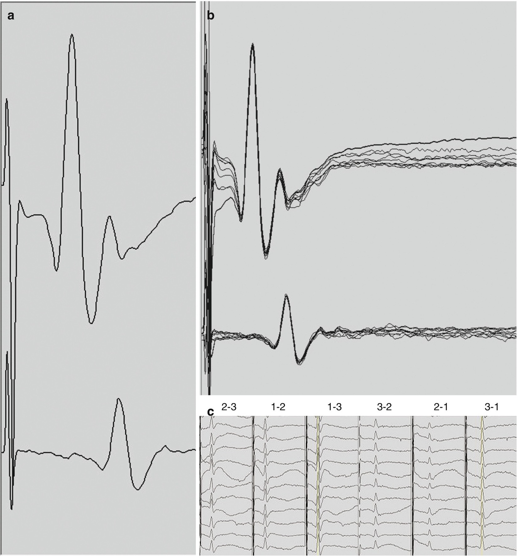
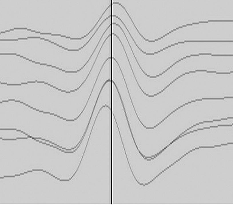
D-waves . (a) D-waves recorded in surgery for a T2 hemangioblastoma from a 3-contact, spinal electrode placed rostral to the lesion (top trace) and caudal to the lesion (bottom trace). D-waves in this panel were obtained with the 1-3 and 3-1 montages which typically produce the largest responses. The latency of the peak of the response is 3.2 and 5.3 msec, and, the amplitude measured from the peak to the base of the trailing trough is 103 μV and 34 μV for the rostral and caudal recordings, respectively. (b) Overlay of 10 consecutive D-waves recorded in the same patient. (c) A selection of the summary of the D-waves. The recording montages are indicated above each column. The three columns on the left are recorded from the rostral electrode while the three columns on the right from the caudal electrode. Display gains were adjusted for clarity and may not be the same across montages
A description of D-wave characteristics and technical aspects of D-wave monitoring and interpretation are described later in the chapter. When the action potentials contributing to the D-wave descending the CST arrive at the respective synaptic targets on the lower motor neurons in the spinal cord they facilitate depolarization. Lower motor neurons are large and have high capacitance; therefore, they require coincident and repetitive excitatory synaptic events to move their membrane potential above the threshold for firing their own action potentials. For this reason, a single electrical stimulus in the proximal motor pathway, while sufficient to initiate a D-wave, is normally insufficient to trans-synaptically generate an action potential in the lower motor neuron. Therefore, to elicit muscle MEPs we employ a train stimulus paradigm. This results in a rapid succession of D-waves, one for each stimulus pulse in the train (and possibly I-waves, described below), arriving at the lower motor neuron, allowing for temporal summation of excitatory inputs.
At an appropriate stimulus train frequency, the corresponding train of D-waves are superior to a single one at raising the membrane potential of the alpha motor neuron above its threshold, driving it to fire its own action potential and activate the respective muscle fibers. The myogenic motor evoked response obtained when a single motor neuron fires an action potential is a motor unit potential (MUP) , whereas that obtained when two or more motor neurons fire is a compound muscle action potential (CMAP) . It is important to note that muscle MEPs (see below) are sometimes difficult to elicit particularly with transcranial stimulation. In general, it is at and above the level of the alpha motor neuron in the spinal cord that we see neurophysiologic complexity in the ability to activate the motor pathway and generate muscle MEP responses.
Transcranial Motor Evoked Potentials
MEPs for intraoperative spinal cord monitoring are initiated by transcranial electrical activation of the motor cortex and descending motor fibers and are therefore called transcranial motor evoked potentials (TcMEPs). Subdermal needle electrodes, often of corkscrew design, are placed in the scalp over the approximate location of the primary motor cortex. This may either be at the 10–20 system-derived positions of C3, C4, C1, or C2 or slightly anterior to each of these positions (the so-called “M” locations). Be prepared to incorporate electrodes along the Z line (down the midline) at the respective positions of 1 cm posterior to, and 6 cm anterior to, CZ, so-called CZ minus and CZ 6 cm, respectively. The stimulus montage of C1–C2 is a good choice as an activation site for TcMEP in IMSCT surgery, and the alternate montages of C3–C4 and CZ minus–CZ 6 cm are incorporated as needed. The more medial the montage, the greater the selectivity of activation of the fibers of the lower extremity, with the midline stimulus montage resulting in the strictest focus on the lower extremities. Placing stimulating electrodes with such a lower-extremity focus may possibly cause optimal upper extremity responses to be sacrificed. The objective of medially derived montages is primarily to reduce otherwise unmanageable patient movement during TcMEP monitoring. It is secondarily to reduce the incidence of bite injuries of the tongue and mouth, an undesirable outcome of the transcranial stimulation. Transcranial stimulation is not specific for the CST and also results in corticobulbar activation and/or local depolarization of the temporalis muscles both of which cause jaw clenching. Always work closely with the anesthesiology team to incorporate an intraoral bite block(s) to protect the patient from bite injuries. Stimulation through C3-C4 appears to impose the greatest risk in this regard.
For TcMEP, activation of the motor pathway favors the side of the brain under the anode and, thus, the muscles of the hemi-body opposite the anode. An optimized stimulus selectively activates the motor pathway for only the hemi-body opposite the anode. For example, employing C3 as the anode, one would expect right limb muscle responses, and vice versa for C4. However, that lateral specificity of muscle responses during IMSCT surgery is less important than obtaining reliable responses in the important distal muscles. Furthermore, I recommend recording from both sides of the body with each stimulus polarity. This helps the surgical neurophysiologist to capture responses even if the cathodic stimulus generates them, and furthermore prevents congenital non-decussating motor pathways from going undetected, which would negatively impact TcMEP interpretation otherwise. Stimulus parameters such as voltage/current intensity, pulse duration, pulses per train and interpulse interval, and stimulation delivery approaches such as double trains and repetitive, “build-up”–style stimulus delivery are all important contributing factors to optimized activation for TcMEP. In general, the “sicker” the spinal cord the higher the required intensity, pulse duration, number of pulses per train and interstimulus interval and the more likely it will require double trains and repetitive stimulation.
TcMEPs are normally large amplitude, high-frequency, bi- or multiphasic responses and their complexity is defined by the number of undulations as well as the overall duration of the waveform. The complexity and duration are in part related to the number of pulses in the transcranial stimulus, such that longer stimulus trains typically result in more complex and longer TcMEP responses. TcMEP response amplitude is determined as the absolute difference between the largest negative deflection and the largest positive deflection (peak to trough, or vice versa). In general, the latency of the TcMEP response, measured at the point of take-off of the first deflection, depends on the distance from the stimulus site and the distance from the spinal cord, so distal limb muscles have longer latencies than proximal muscles of the same limb. Determining the absolute latency of TcMEP responses during IONM is difficult because it is not known which pulse in the stimulus train is responsible for initiating the response unless the number of pulses in the train is decreased to the point at which the response disappears. This is not a common practice in the operating room, since the absolute latency of TcMEP responses is much less critical to their application and interpretation. TcMEP responses are usually obtained from a one stimulus–one response approach and not normally averaged. In the case of irreconcilable noise, TcMEP responses may be averaged over a few consecutive trials. It is important to keep in mind that TcMEP responses inherently vary from trial to trial.
TcMEP responses are obtained from intramuscular or subdermal needle electrodes placed in or near the belly of the muscles of interest. Since TcMEPs are large, high-frequency responses, a LFF of 10–100 Hz, a HFF of 1500–3000 Hz are appropriate, and a high amplifier sensitivity of 500–3000 μV/Div is necessary to avoid clipping of the waveform which would make amplitudes uninterpretable. Start with an acquisition sweep of 100 msec and consider stretching this acquisition to be able to capture lesion induced delayed responses, particularly for distal muscle groups. Display gain should be initially set at 50–100 μV/Div in order to be able to resolve small responses and adjustments to optimize visibility are often warranted. Tracking the display gains is important particularly when TcMEP data changes occur.
A wide distribution of muscle recording sites is recommended. Proximal and distal muscle groups of the lower extremity such as quadriceps, tibialis anterior and foot muscles are recommended in all cases. Anal sphincter recordings may be included as well. For cervical lesions, segmental and suprasegmental muscles should be included. Proximal “control” muscles should be included whenever possible.
Myelogenic Motor Evoked Potentials: D-Waves
D-waves may be elicited by electrical stimulation delivered directly to the descending CST fibers in the spinal cord or in the brain [26–28]. In general, direct stimulation like this is used for mapping and localization. For monitoring D-waves during IMSCT surgery the most common method of activation is transcranial stimulation similar to that employed for TcMEP: electrical pulses delivered to scalp electrodes strategically placed near the motor cortex.
There are important differences between transcranial activation of the motor pathway for TcMEP recording and that for D-wave recording. To obtain D-waves we employ a stimulus of 50–500 μsec (or more) as a single pulse, rather than a train of pulses, since the lower motor neuron and its dependence on temporal summation are excluded during D-wave recording. As a result, patient movement is reduced or eliminated, permitting nearly continuous sampling of D-waves throughout the time the spinal electrode(s) is/are in place. The stimulus for eliciting a D-wave is delivered in such a manner as to obtain responses that correspond to simultaneous activation of both the left and right CST to capture the entire motor axis. To increase the likelihood of this, the C3–C4 scalp electrode positions are favorable, although the other transcranial stimulating electrode positions are also useful and maintain the benefits of focal activation. These more medially located stimulation sites are of greater use in thoracic IMSCT surgery.
Related posts:


Stay updated, free articles. Join our Telegram channel

Full access? Get Clinical Tree


