Cervical Spine: Plain Radiography


Cervical Spine: Plain Radiography


Philip A. Meinhardt

Alden R. Milam

Bruce V. Darden II


Plain radiography has long been the primary means of imaging the cervical spine. This method is inexpensive, reliable, and readily available. Newer techniques such as CT scan and MRI have advanced the way we image the spine but do not substitute for the information provided by plain x-ray. Radiographs are mandatory for preoperative planning and can be a useful screening tool. They are also frequently used to monitor patients postoperatively and readily show changes over time. Progression of fusion is easily documented by plain radiography as well as maintenance of alignment. Although newer modalities provide us with additional information, they have not supplanted plain radiographs.

Lateral, anteroposterior, and open-mouth views represent routine radiographic evaluation of the cervical spine. Additional projections, such as flexion-extension, swimmer’s, and oblique views, can be employed when necessary. Flexion-extension views are useful when assessing for fusion or evaluating instability. Visualization of the upper thoracic spine such as the T1 vertebra or C7-T1 disk space can be facilitated by obtaining a swimmer’s view. Oblique views allow for visualization of the facet joints and neural foramina. Adequate images and careful interpretation in the setting of trauma can produce sensitivity of fracture detection as high as 93% (1).


GENERAL X-RAY INTERPRETATION


LATERAL VIEW (FIGS. 23.1, 23.2 and 23.3)

The lateral view is a critical part of the radiographic evaluation of the cervical spine. A lateral x-ray must include the base of the skull to the cervicothoracic junction. The inability to adequately view the upper border of T1 results in an incomplete study. Alignment of the cervical spine can be assessed by evaluating the four lines of the cervical spine: (a) anterior vertebral, (b) posterior vertebral, (c) spinolaminar, and (d) spinous process lines. These lines should be smooth and continuous with no step-offs or discontinuity. The only exception is up to 2 mm of posterior displacement of the spinolaminar line at C2. The spinous processes should be equidistant, and any widening of the interspinous distance should raise concern for an injury to the posterior ligamentous complex. Subluxation of one vertebra on another should be carefully scrutinized. A unilateral facet dislocation will produce no more than 50% subluxation. If greater than 50% subluxation is present, a bilateral facet dislocation should be suspected. This is typically accompanied by widening of the interspinous and interlaminar spaces. There should be a smooth lordotic curve throughout the cervical spine. Loss of lordosis can be secondary to age, trauma, muscle spasm, or positioning. The heights of the anterior and posterior aspects of each vertebral body from C3 to T1 should be the same. A disparity of greater than 2 mm suggests a compression fracture. A disparity greater than 25% suggests an injury to the posterior ligamentous complex. The bony elements should be intact with no evidence of abnormal density or cortical discontinuity. The anterior atlantodens interval (AADI or ADI) should be evaluated for excess widening (see later in the chapter for full discussion). The diameter of the spinal canal is measured from the posterior border of the vertebral body to the spinolaminar line. This measurement should be greater than 13 mm at all levels. Values less than 13 mm can represent a traumatic injury or stenosis from a congenital or acquired abnormality. The disk spaces and facet joints should be preserved and free of narrowing or sclerosis (2). Look for any differences between levels and take note of abnormal ossification, either anterior or posterior to the vertebral bodies. With spondylotic degeneration, there will often be posterior spurring at the disk level. The location of this posterior spurring seen on the lateral x-ray may be either of the uncovertebral joints (joints of Luschka) or the end plates. The anteroposterior radiograph is useful to determine exactly where the spurs are occurring as the uncovertebral joint can be readily seen on this view, and osteophytes can be seen adjacent to the uncinate process. Careful attention should be paid to soft tissue shadows anterior to the vertebral bodies (Table 23.1, normal values). This can be a subtle clue to a significant injury producing a hematoma and compressing the oropharynx.


ANTEROPOSTERIOR VIEW (FIG. 23.4)

The anteroposterior view should undergo similar scrutiny to the lateral view. An adequate exam should include C3-T1. The upper cervical vertebrae are typically obscured
by the occiput and mandible. The spinous processes and facet joints should be symmetric and well aligned. Any abnormal rotation of a single spinous process can indicate a unilateral facet dislocation and rotational malalignment to the side of the injury. Attention should be paid to any abnormalities in bony architecture. The intervertebral disk and facet joints should be symmetric and preserved. Look for evidence of asymmetry in the paravertebral soft tissues (3). Evaluate the uncovertebral joints for any signs of degeneration including loss of joint space, sclerosis, and lateral spurring.


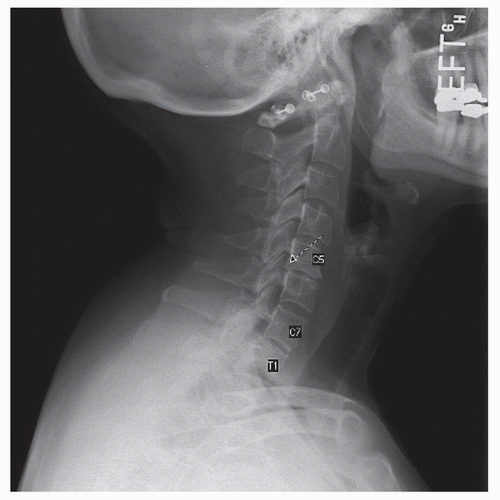
Figure 23.1. Adequate lateral x-ray. C7-T1 level is visualized. Note the disk space collapse at C5-C6 and the end plate spurring at that level, noted by arrow.


OPEN-MOUTH VIEW (FIG. 23.5)

The odontoid or open-mouth view shows the C1-C2 articulation. The distance between the medial border of the lateral mass of C1 and the dens should be symmetric. There should be less than 2 mm of lateral overhang of C1 on C2. Combined lateral overhang of greater than 7 mm is never normal and may represent a Jefferson fracture or rupture of the transverse ligament in a Jefferson fracture. The C1-C2 articulations should be parallel with preserved height and no narrowing or sclerosis. The border of the dens should be smooth and rounded with no cortical disruption.


SPECIALIZED VIEWS (FIGS. 23.6 AND 23.7)

Specialized views can be obtained as indicated. The swimmer’s view is used to show the cervicothoracic junction when the lateral projection is inadequate. The main information garnered from this view is alignment of the anterior vertebral bodies. The cervicothoracic junction must be visualized for complete trauma evaluation. A study of 100 trauma patients over a 2-year period looked at the adequacy of the swimmer’s view in evaluation of the cervicothoracic junction. They found that only 55% of the swimmer’s views provided adequate visualization of the cervicothoracic junction, and CT scan was recommended to completely evaluate this area (4). Oblique views are used to image the intervertebral foramina and facet joints. They can be useful in the case of a suspected facet fracture or dislocation. Flexion and extension views are used to show any abnormal motion between vertebrae. They can be particularly useful to evaluate for fusion between levels. The main measurement in this case is the interspinous distance. Less than 2 mm difference in the interspinous
distance with flexion and extension indicates fusion at the levels in question. These images should be used cautiously in the case of suspected trauma. CT or MRI may be safer and of greater utility in this situation.


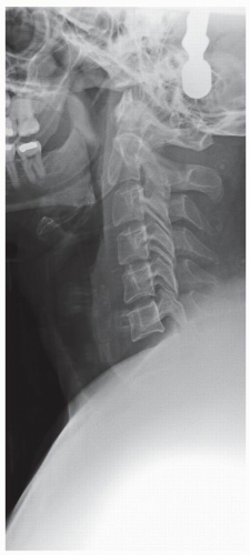
Figure 23.2. Inadequate lateral x-ray. Top of C7 level is not visualized.


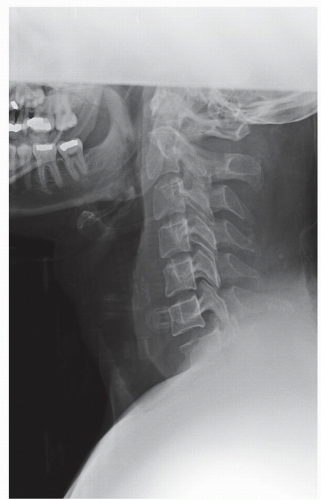
Figure 23.3. Once C7 level is visualized on lateral x-ray, a bilateral jumped facet at C6-C7 can be seen. There is greater than 25% anterolisthesis of C6 on C7.


ATLANTOAXIAL INSTABILITY (FIG. 23.8)

The AADI or ADI has traditionally been used as a measure for atlantoaxial instability. The AADI is the distance between the posterior edge of the anterior ring of C1 and the anterior surface of the odontoid process. In adults, the AADI should be less than 3.5 mm of translation on flexion and extension views (5). This measurement should be less than 5 mm in the pediatric patient (6). It is important to note that these values were obtained from evaluation of normal cervical spines. These values may not be applicable to specific disease states. An example of this is the case with Down’s syndrome where larger values may be considered normal. This will be discussed separately later in this chapter. It has been suggested that the posterior atlantodens interval (PADI) may be more useful in identifying patients at risk for neurologic compromise. The PADI is the distance between the posterior border of the odontoid process and the anterior margin of the posterior ring of C1. This measure is a reflection of the space available for the cord (SAC). Boden et al. found that the PADI correlated with severity of neurologic symptoms in rheumatoid patients with atlantoaxial instability. In this study, 60% of 32 patients had an AADI that did not equal or exceed the common operative criteria of 9 mm despite these patients being paralyzed. In contrast, a PADI of less than or equal to 13 mm was present in all but one of these patients. The PADI was also predictive of neurologic recovery in these patients; no patients with a PADI less than 10 mm having
any substantial return of neurologic function. The conclusion of this study was that patients with a PADI of 14 mm or less should undergo operative stabilization (7).


TABLE 23.1 Normal Prevertebral Soft Tissue Width


Level


Flexion, mm (Range)


Midposition, mm (Range)


Extension, mm (Range)


C1


5.6 (2, 3, 4, 5, 6, 7, 8, 9, 10 and 11)


4.6 (1, 2, 3, 4, 5, 6, 7, 8, 9 and 10)


3.6 (1, 2, 3, 4, 5, 6, 7 and 8)


C2


4.1 (2, 3, 4, 5 and 6)


3.2 (1, 2, 3, 4 and 5)


3.8 (2, 3, 4, 5 and 6)


C3


4.2 (3, 4, 5, 6 and 7)


3.4 (2, 3, 4, 5, 6 and 7)


4.1 (3, 4, 5 and 6)


C4


5.8 (4, 5, 6 and 7)


5.1 (2, 3, 4, 5, 6 and 7)


6.1 (4, 5, 6, 7 and 8)


C5


17.1 (11, 12, 13, 14, 15, 16, 17, 18, 19, 20, 21 and 22)


14.9 (8, 9, 10, 11, 12, 13, 14, 15, 16, 17, 18, 19 and 20)


15.2 (10, 11, 12, 13, 14, 15, 16, 17, 18, 19 and 20)


C6


16.3 (12, 13, 14, 15, 16, 17, 18, 19 and 20)


15.1 (11, 12, 13, 14, 15, 16, 17, 18, 19 and 20)


13.9 (7, 8, 9, 10, 11, 12, 13, 14, 15, 16, 17, 18 and 19)


C7


14.7 (9, 10, 11, 12, 13, 14, 15, 16, 17, 18, 19 and 20)


13.9 (9, 10, 11, 12, 13, 14, 15, 16, 17, 18, 19 and 20)


11.9 (7, 8, 9, 10, 11, 12, 13, 14, 15, 16, 17, 18, 19, 20 and 21)


Notes: The midposition widths were measured on lateral radiographs of 50 noninjured patients, who were normal except for varying degrees of cervical spondylosis in some; their average age was 46 years (range, 15-78 years). Widths in flexion and extension were measured in 20 patients with normal prevertebral widths in midposition; their average age was 31 years (range, 16-67 years). The sites of measurement are shown in Figure 24.5. No correction has been made for radiologic magnification (about 1.3). From Penning L. Prevertebral hematoma in cervical spine injury: incidence and etiological significance. Neuroradiol 1980;1:557-565, with permission.

Only gold members can continue reading. Log In or Register to continue

Stay updated, free articles. Join our Telegram channel

Jul 5, 2016 | Posted by in NEUROSURGERY | Comments Off on Cervical Spine: Plain Radiography

Full access? Get Clinical Tree

Get Clinical Tree app for offline access