Spinal Instrumentation in Degenerative Disorders of the Cervical Spine
Thomas Walter Lawhorne III
Lukasz Curylo
Howard S. An
HISTORICAL PERSPECTIVE
Early spinal fusions were performed for stabilization of spinal tuberculosis. Studies by Albee (1) and Hibbs (2) reported a high complication and death rate (40%). Such fusions were performed as stand-alone structural grafts and required prolonged bed rest or cast immobilization. First reports of cervical fusion were published by Cloward and Smith-Robinson and involved noninstrumented cervical spine fusions with a high nonunion rate (3, 4, 5 and 6).
The use of anterior cervical plate/screw fixation was first reported by Bohler (7) in 1967. Ventral cervical instrumentation was initially used in cervical trauma. However, due to obvious benefits of this instrumentation, the indications for its use have been expanded to degenerative cases including multilevel decompressions, allograft use, and smoking. The mechanical design of ventral cervical plating initially involved nonconstrained designs. Subsequently, due to an increased failure rate of nonconstrained implants, a “locking” screw design was incorporated into contemporary ventral plates (8). Multiple designs of ventral plates exist, including both static and dynamic designs. Most recently, load-bearing devices have been investigated in cervical spine fusions. Multiple designs of ventral cervical fusion cage designs are currently undergoing clinical trials as stand-alone devices (9,10).
Dorsal spine fusion results were initially published in nondegenerative cases. Initially, wiring was reported for treatment of Pott’s disease by Hadra (11) in 1891. Rogers et al. published the first report of dorsal interspinous wiring in 1942, describing fixation of cervical fractures and dislocations (12). Since then, numerous reports of various dorsal interspinous and facet wiring techniques have been published. Certainly, even today this simple technique remains a viable option for enhancing dorsal fusion, either as a stand-alone construct or in combination with dorsal lateral mass plating.
Dorsal cervical plate fixation is a relatively more recently employed technique. It was initially used by Roy-Camille and Saillant (13) in 1970 and popularized by Cooper and Cohen (14) in 1988. Initially reported in the trauma literature, its uses have since been expanded to primary and revision degenerative disorders. Again, since then several variants of lateral mass plating technique have been published by An et al. (15), and Anderson and Henley (16). Initial reports involved the use of nonconstrained systems. Recently, fixed angle or “locking” rod/screw polyaxial designs are gaining popularity due to increased stability and ease of application.
VENTRAL CERVICAL FIXATION
INDICATIONS
With the recent advancements in surgical technique and material engineering, ventral cervical instrumentation is gaining popularity. It offers several benefits over noninstrumented fusions by increasing the likelihood of a solid union, decreasing graft-related complications, and allowing for minimum postoperative immobilization.
Ventral plating can neutralize suboptimal biomechanical conditions in multilevel ventral decompressions and fusions. Multilevel discectomies have decreased fusion rates because of the decreased stability and increased micromotion. Graft dislodgment in noninstrumented single-level anterior cervical discectomy and fusion (ACDF) is reported from 2% to 4.6%, and it is even higher in noninstrumented multilevel fusions from 10% to 29% (17). Despite this, nonunion rates in instrumented versus uninstrumented single-level ACDF is similar, at around 5% to 10% (18,19). Nonunion rates are 20% to 27% in twolevel ACDF and an unacceptably high rate of 30% to 63% in uninstrumented three-level fusions (18,20,21).
Plating is especially important in suboptimal biologic environments such as use in smokers and when using allograft bone. Smoking is a well-known cause of increased pseudoarthrosis rate. The adverse effect of nicotine on graft incorporation and vascular ingrowth into autologous
graft has been well demonstrated in animal models (22). Hillibrand et al. (23) have shown an overall doubling of nonunion rate from 19% to 38% in smokers with noninstrumented ventral cervical procedures. In this series, the nonunion effect was most pronounced in patients undergoing multilevel anterior cervical discectomy and interbody grafting, where the pseudoarthrosis increased from 24% to 50% in smokers. The effect of nicotine increases the nonunion rate from 27% to 47% (24).
graft has been well demonstrated in animal models (22). Hillibrand et al. (23) have shown an overall doubling of nonunion rate from 19% to 38% in smokers with noninstrumented ventral cervical procedures. In this series, the nonunion effect was most pronounced in patients undergoing multilevel anterior cervical discectomy and interbody grafting, where the pseudoarthrosis increased from 24% to 50% in smokers. The effect of nicotine increases the nonunion rate from 27% to 47% (24).
Instrumentation also increases the rate of fusion, often allowing the use of less optimal grafting material such as allograft bone (25). Thus, donor site morbidity related to bone graft harvesting can be avoided. Fernyhough et al. have demonstrated in a series of 126 patients the increase of nonunion rate in patients with allograft (41%) as compared to the autograft group (27%) when uninstrumented. Certainly, a combination of smoking and allograft has an even greater effect on union. Bishop et al. (26) in a prospective study of 132 patients have shown a significantly decreased fusion rate in smokers receiving allograft for cervical interbody fusions.
Ventral plating prevents late deterioration of the alignment obtained at surgery and thus prevents delayed neurologic deterioration. This is essential in multilevel fusions as the prevalence of pseudoarthrosis increases with the number of levels operated upon (27). Emery et al. (28) showed a 4.3- to 6.5-degree increase in cervical kyphosis in noninstrumented three-level ACDF.
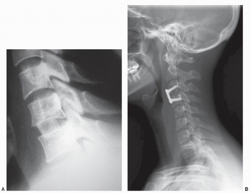 Figure 83.1. A: Example of a successful nonplated single-level ACDF using autograft bone. B: Example of a successful single-level ACDF using allograft bone. |
Ventral instrumentation can also be used in revision cases involving a pseudoarthrosis. Tribus et al. (29) have demonstrated an 81% fusion rate in ventral nonunions revised with ventral plating. It is indicated especially when allograft bone is used for such nonunion repair (30).
The postoperative course is favorably altered by allowing the use of less constrained cervical orthoses for postoperative immobilization. Rehabilitation time is often shortened and resultant cost savings are obvious.
Single-level ACDF in a nonsmoker and with use of iliac crest autograft is usually performed without fixation (Fig. 83.1A and 83.1). It is the authors’ preference to use plating in all single-level ACDF patients but in particular when using allograft bone or in smokers (Fig. 83.1B). Plating is also used for all multilevel ACDF and for one- and twolevel corpectomies (Fig. 83.1C and D.) Segmental fixation in such cases is recommended. However, due to potential complications of ventral plating of three- and four-level corpectomies, the authors prefer in such cases to combine an instrumented ventral strut fusion with a dorsal
cervical fusion using lateral mass plating or to use rigid postoperative immobilization. Often, corpectomies can be performed at the most severely involved levels and can be combined with ACDF at less involved areas (31). Thus, more stable segmental fixation constructs can be achieved (Fig. 83.1E).
cervical fusion using lateral mass plating or to use rigid postoperative immobilization. Often, corpectomies can be performed at the most severely involved levels and can be combined with ACDF at less involved areas (31). Thus, more stable segmental fixation constructs can be achieved (Fig. 83.1E).
 Figure 83.1. Continued C: Example of a successful ventral fixation with segmental screws following two-level discectomy and fusion with allograft. D: Example of a three-level ACDF using nonsegmental terminal screws. Use of rigid postoperative immobilization is strongly advised in this case. E: Variant of a ventral plate with terminal screws of single-level corpectomy and fusion with iliac crest allograft and corpectomy autograft bone chips. F: Example of a ventral plate with terminal screws and intermediate screws following corpectomy at one level and discectomy at another level with fusion with iliac crest allograft and corpectomy autograft bone chips. This “semisegmental” fixation gives superior stability over long strut graft with terminal screws alone. |
RATIONALE
Ventral plates increase the stiffness of fusion constructs and increase fusion rates. They also decrease graft-related complications.
Ventral plating systems have been refined through multiple modifications. First-generation plates merely used parallel slots for the screws that did not lock or constrain to the plate. The plate allowed settling at the cost of frequent screw backout and loss of stability (32). Bicortical screw placement into the vertebral bodies could offer improved pullout strength in flexion/extension as compared to unicortical screws as shown by Ryken et al. (33) in a cadaveric study. Bicortical screw fixation provides also additional stability in cyclic loading (34). Unlocked bicortical screw purchase offers no additional stability as compared to a locked unicortical screw/plate system (Fig. 83.2A) (35). These locking systems allow for more rigid fixation with less risk of collapse or cutout. Smith et al. demonstrated in biomechanical studies that locking of cervical screws to the plate provides additional stability under large angular displacement when comparing to nonlocking plates (36,37). Multiple studies have demonstrated the high efficacy of locked unicortical screw/plate systems (Fig. 83.2B and C) in stabilizing degenerative cervical disorders. These rigid implants are criticized because they can prevent load sharing with the interbody graft by stress shielding. Therefore, ventral cervical systems were created that allow dynamic axial compression across a fusion site. There are various ways in which dynamization is permitted, varying from screws toggling within the screw hole, screw translation in a slotted screw hole, and telescoping plates that move together during settling. Such systems theoretically increase the healing rate by allowing for dynamic graft/end plate axial compression while maintaining the rotatory and flexion/extension stability comparable to static locking plates (38). Initial clinical results are encouraging and show a 94% to 95.7% fusion rate with a 4.3% of graft/hardware complications, using dynamic plates (39,40). There have been no
double-blind studies comparing dynamic and rigid ventral cervical plates to date. Dynamic plates systems may not provide rigid enough fixation for unstable fractures, and more long-term results are needed for three- or four-level fixation following multilevel corpectomy.
double-blind studies comparing dynamic and rigid ventral cervical plates to date. Dynamic plates systems may not provide rigid enough fixation for unstable fractures, and more long-term results are needed for three- or four-level fixation following multilevel corpectomy.
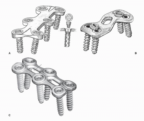 Figure 83.2. A: Example of a plate with locking ventral screws. Locking mechanism is engaged by expansion of the screw head by a smaller interference screw. B: Example of a plate with a locking mechanism engaged by an accessory screw. Polyaxial screw design is present. C: Example of a plate with a locking mechanism engaged by a screw/bushing interference fit. Polyaxial screw placement is possible. |
Vanichkachorn et al. (41) have reported the ventral buttress plate technique as a technique that theoretically may prevent or decrease the incidence of graft or internal fixation dislodgement in long segmental cervical fusions. It must be stressed that three- or four-level corpectomy cases are challenging to restore biomechanical stability with ventral fixation alone, and dorsal supplemental fixation should be considered. If dorsal segmental fixation is used, ventral buttress plate or any internal fixation other than bone graft probably is not needed (31).
TECHNIQUE
For access to the lower cervical spine, the classic ventromedial Smith-Robinson approach is used (42). Incisions in line with Langer’s skin lines are most commonly used and extend from midline to the lateral border of the sternocleidomastoid muscle. Occasionally, oblique or longitudinal incisions can be used for access to more than three cervical levels; however, cosmesis is inferior to transverse incisions due to scarring and contractions. The subcutaneous tissue, platysma, and the deep cervical fascia are cut in line with the skin incision. The platysma muscle can be undermined rostrally and caudally to gain access to more cervical levels. Care must be taken to avoid bleeding from large branches of the anterior jugular vein by their ligation or careful retraction. Next, gentle finger blunt dissection is done through the interval between the medial sternocleidomastoid muscle and the strap muscles. Once a plane is developed, it can be expanded proximally and distally to increase exposure. Care must be taken to retract the carotid sheath and its contents laterally by palpating the carotid pulse. Also commonly encountered, inferior thyroid artery must be protected or suture ligated. A smooth retractor is then used to retract the tracheoesophageal structures medially and the sternocleidomastoid muscle laterally. Tension on the retractors allows for visualization of the pretracheal and the prevertebral fascia directly overlying the ventral cervical spine. Both these layers are then bluntly spread in the longitudinal direction to allow for direct surgical access to the disks and vertebral bodies. The longus colli muscle is then undermined. Self-retaining smooth blade retractors are positioned underneath this muscle to prevent injury to the medially laying tracheoesophageal structures and the lateral carotid sheath. Depending on the level of the skin incision, the levels from C2 to T1 can be visualized with this approach. Next, depending on the degenerative pathoanatomy, decompression is performed by a discectomy or corpectomy, as described elsewhere in the textbook. This is followed by preparation of end plates and graft-docking sites. Next, about 2 mm of distraction is applied and appropriate length allograft or autograft is inserted (43). For ACDF, a 3-mm hole can be made in the middle of the superior and inferior end plate to improve vascularity while preserving the end plate strength (44) (Fig. 83.3).
 Figure 83.3. A single, central hole in the end plate was found to have improved biomechanical properties than smaller paired or multiple holes. |
The instrumentation phase begins with selection of plate length. Using calipers, the distance from midpoints of terminal vertebrae is measured and an appropriate length ventral plate is chosen. An appropriate length plate should not impinge on disk spaces adjacent to the planned fusion, which are not being fused. This has been associated with adjacent-level ossification across the disk space (45). The plate is next contoured to match the radius of cervical lordosis. Ventral osteophytes are removed with a rongeur or burr in order to enlarge the plate contact surface. Prior to placement of the plate, the midline of the vertebral bodies is marked, so that it can be aligned with the long axis of the plate. Several landmarks can be used to identify the midline of each vertebral body: the peak of the convex contour of the body (in the medial-lateral direction) or the middle of the distance from the right to left longus colli. The plate is then fixed with temporary pins, and the plate alignment is assessed. If necessary, portable radiographs can confirm the plate position. Compression is then applied at the terminal vertebrae either indirectly by removing traction or via direct compression (using a Cloward distractor). Depending on the surgeon’s preference, unicortical or bicortical screw holes are then drilled using standard technique. For unicortical screws, a drill stop at 14 to 16 mm is recommended to prevent unwanted dorsal cortex penetration (46). Screws should be either parallel or angled superiorly for the proximal screws, and the inferior screws are parallel to end plate surfaces for optimal stability. Before final tightening, an intraoperative lateral radiograph will confirm proper intraosseous screw placement and the graft position. Most system manufacturers provide larger diameter “salvage” or “emergency” screws, if previously misplaced screws need to be redirected and redrilled. During final tightening, the screw-locking mechanism must be engaged and verified.
For ventral access to C1-C2, modified approaches must be used. A lateral approach of Whitesides, a ventral retropharyngeal approach of McAfee, or a transoraltranspharyngeal decompressive approach as described by Fang et al. can be used (47,48). With either approach, ventral C1-C2 fixation can be performed with a plate or by placement of transarticular ventral to dorsal screws as described by Vaccaro et al. (49,50).
INDICATIONS
Dorsal cervical fusions are often performed in degenerative diseases of the upper and lower cervical spine.
Uncommonly, degenerative changes occur at the atlanto-occipital and atlantoaxial facet joints with a documented 4.8% incidence (51). In such advanced cases, patients often fail conservative treatment. Occipitocervical and C1-C2 fusions can be used in such instances, especially when degeneration is a result of trauma or instability.
More commonly, dorsal cervical fusions are done for primary degeneration of the lower cervical spine. Instrumentation is often used to increase rigidity of such fusion constructs and maintain alignment until fusion occurs. Oftentimes, dorsal fusions are used as salvage techniques in cases of pseudoarthrosis after attempted ventral fusions. Historically, interspinous wiring techniques are indicated for single- and multiple-level fusions of the lower cervical spine in cases with intact dorsal elements. This technique should be commonly employed in conjunction with rigid postoperative bracing. Dorsal plate or rod systems using lateral mass and/or pedicle screw fixation technique provides stronger stabilization and is currently treatment of choice. It is routinely used to stabilize and prevent postoperative kyphosis in multilevel dorsal fusions and in cases of dorsal decompression by laminectomies and foraminotomies (52, 53 and 54). Dorsal instrumentation is also indicated in circumferential cervical fusions and in cases where the fusion crosses the cervicothoracic or occipitocervical junction. Need to eliminate or limit external postoperative immobilization and the need for early mobilization is another relative indication (14,16).
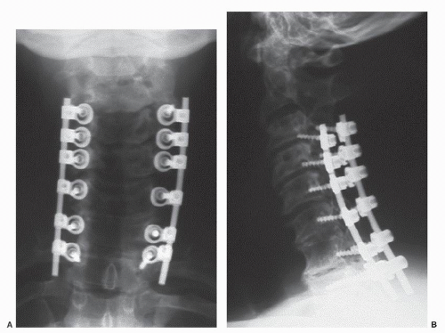 Figure 83.4. A,B: Example of dorsal multilevel fusion using lateral mass screws and rods following a multilevel laminectomy. Immediate postoperative AP and lateral radiographs are shown. |
The authors routinely use dorsal instrumentation in a lateral mass fusion construct with multilevel laminectomies (Fig. 83.4A and B). This is often performed for patients with multilevel bilateral myeloradiculopathy who present with neck pain, instability, and loss of cervical lordosis. The authors, however, prefer a noninstrumented laminoplasty technique if symptoms are unilateral, patients have minimal neck pain, and a lordotic cervical spine.
RATIONALE
Multiple in vitro biomechanical studies have investigated the rigidity provided by various dorsal fixation methods in the lower cervical spine (55, 56 and 57).
Gill et al. evaluated dorsal plating techniques with lateral mass fixation. They have shown the superior stability of lateral mass plates with bicortical screws as compared to interspinous wiring and lateral mass plating with unicortical screws (58). Bicortical lateral mass screws are superior to unicortical screws as shown by Heller et al. (59). Sutterlin and McAfee (55) have demonstrated the increased stiffness of dorsal plating when compared to ventral plating techniques.
Dorsal instrumentation with pedicle screw fixation provides even higher stability. It is superior to both lateral mass instrumentation and ventral plating (60). Unfortunately, use of this technique is limited due to cervical anatomy with narrow pedicles and possibility of serious neurovascular complications (61). The only recommended sites for pedicle screw placement are C2, C7, and T1. The prevalence of fusion in patients treated with instrumentation is better than that in patients treated with bone grafting alone (53,62,63). Also, upper cervical spine fixation methods have been extensively studied in vitro (64).
TECHNIQUE
Dorsal fixation is performed under general or local anesthesia with adjunctive intravenous sedation (65). The patient is positioned prone in cranial tong traction or a Mayfield head holder. In cases of myelopathy, severe stenosis, or instability, fiber optic intubation is used, and the patient is turned on a Stryker table or rotating Jackson table. A pre- and postpositioning neurologic check is routinely performed. The neck should be positioned in neutral or in slight extension, and it should not be translated ventrally. If the optimal alignment or positioning is deemed dangerous due to severe stenosis, the neck should be in a flexed position and after decompression realigned prior to instrumentation. A lateral radiograph also insures optimum positioning, as lateral mass instrumentation has minimal ability to correct malalignment. A midline approach through the dorsal cervical raphé allows access to the occipital protuberance, spinous processes, and lamina and minimizes intraoperative bleeding. Paraspinal muscles are subperiosteally elevated at the desired levels. During the exposure, care must be taken at the superior margin of C1 arch. If the dissection is more than 1.5 cm lateral to midline, significant risk of vertebral artery (VA) injury exists. Also, the venous plexus between C1 and C2 should carefully be exposed to avoid bleeding.
Multiple sites are available for dorsal fixation placement: the occipital bone; the laminae and transverse processes at all cervical levels; the pedicle at C2, C7, and T1; and the lateral masses at C3 to C7.
For occipitocervical fusion, several techniques have been described: Bohlman triple-wire technique, dorsal plating, and the Ransford-Crockard loop (66,67). For purposes of fixation, Haywood et al. (68) mapped the occipital bone thickness. The thickness ranges from 3 to 17 mm depending on the relation to midline and to the external occipital protuberance. Either unicortical or bicortical 3.5-mm screws can be placed, except for areas at the level or superior to the external occipital protuberance. The proximity of the superior sagittal sinus and the transverse sinus precludes bicortical screw placement. Typical screw length is 6 to 12 mm.
Related posts:
 Cervical Orthoses and Cranioskeletal Traction
Neurologic Examination: Grading Scales
Computed Tomography and Myelography of the Cervical Spine
Pediatric Spinal Cord Injury
Spinal Cord Injury: Assessment and Neurologic Classification
Subaxial Cervical Injuries: Current Concepts in Classification and Treatment
Cervical Orthoses and Cranioskeletal Traction
Neurologic Examination: Grading Scales
Computed Tomography and Myelography of the Cervical Spine
Pediatric Spinal Cord Injury
Spinal Cord Injury: Assessment and Neurologic Classification
Subaxial Cervical Injuries: Current Concepts in Classification and Treatment
Stay updated, free articles. Join our Telegram channel

Full access? Get Clinical Tree


