Functional Anatomy of Joints, Ligaments, and Disks
Alpesh A. Patel
William Ryan Spiker
Alexander J. Ghanayem
The human cervical spine has a unique anatomy adapted to allow a mobile head-torso transitory zone while protecting the spinal cord and accompanying neurovascular structures with anatomic restraints. Most of the information on the protection provided by these restraints is derived from postmortem analysis of fatal cervical spine injuries and biomechanical studies of cadaveric specimens (1, 2, 3 and 4). Clinical and radiographic studies have also aided in defining the normal function of cervical joints and soft tissues (5, 6, 7, 8, 9, 10 and 11). Disturbance of the anatomy or the physical and mechanical properties of the elements of the cervical spine may lead to clinical symptoms. The upper cervical spine segment (C0-C1-C2) and the lower cervical spine (C3 through C7) have distinct anatomic and functional features and are thus described separately.
UPPER CERVICAL SPINE
The upper cervical spine includes the occipitoatlantal (C0-C1) and the atlantoaxial (C1-C2) joint complexes (Figs. 3.1, 3.2 and 3.3). Anatomic characteristics include the absence of intervertebral disks, the absence of ligamenta flava, and the distinct osseous anatomy of C1 and C2. Motion is coupled between the two joints, which share a common embryonic origin. Instead of an intervertebral disk in the occipitoatlantal level, the developmental process results in the formation of the apical and alar ligaments as well as the cranial portion of the dens. In the atlantoaxial level, the caudal part of the C1 somite and the cranial part of the C2 somite fuse to form the odontoid process. The odontoid process begins to fuse with the body of C2 at 4 years of age; this fusion is complete by age 7. Almost onethird of adults will have a remnant of cartilaginous tissue between the odontoid and the body of C2 (12).
Bony morphology and the attachments of ligaments that can span over two articulations define the kinematics of the C0-C1-C2 complex. The complex is responsible for 40% of total cervical flexion-extension and 60% of total cervical rotation. Although in this chapter functional anatomy is described separately for the C0-C1 and C1-C2 segments, one should remember that these two motion segments are intimately linked and the motion is coupled.
OCCIPITOATLANTAL JUNCTION
Motion in the sagittal plane is the primary function at the occipitoatlantal junction and is reported on average as being between 13 degrees (13) and 25 degrees (10). The C0-C1 joints have a cup-shaped configuration that is deeper in the coronal plane. Flexion of C0-C1 is limited by the tip of the dens impinging on the ventral margin of the foramen magnum, on what Werne (13) has described as the bursa apicis dentis. The tectorial membrane inserts at the body of C2 and the ventral rim of the foramen magnum and limits extension. Interestingly, flexion at C0-C1 rolls the upper part of the membrane taut, limiting flexion at the C1-C2 level. Translation at this junction is minimal under normal conditions. Flexion and extension should result in no more than 1 mm of translation between the basion and tip of the dens (14).
Axial rotation and lateral bending in C0-C1 are limited to about 5 degrees on each side and are controlled by the capsules and the alar ligaments (Fig. 3.4). The alar ligaments are symmetrical on both sides and about 10 to 13 mm long, with one portion connecting the dens to the occiput and the remaining ligament connecting the dens to the atlas (15,16). During left lateral bending, the right upper component (connected to the occiput) and the left lower component (connected to the ring of C1) become taut. When the head rotates to the left, both components of the right ligament become taut. The instantaneous axis of rotation (IAR) for the C0-C1 articulation has not been defined, although the x-axis is considered to pass through the mastoids and the z-axis is considered to be 2 to 3 mm above the tip of the dens.
Compressive sagittal plane translation (z-axis) is minimum under normal conditions because of the cup-shaped articular anatomy. Distraction of the joint complex is restricted mainly by the tectorial membrane, with minor contribution from the alar ligaments. The apical ligament and anterior and posterior atlantooccipital membranes
have not been found to contribute against distraction (13,15,17, 18 and 19). However, a recent biomechanical evaluation of vertical distraction injuries revealed that variations in the anatomy of the superior cruciate ligament, inferior cruciate ligament, and alar ligaments determined if distraction occurred at the occipitoatlantal junction or the atlantoaxial level (20).
have not been found to contribute against distraction (13,15,17, 18 and 19). However, a recent biomechanical evaluation of vertical distraction injuries revealed that variations in the anatomy of the superior cruciate ligament, inferior cruciate ligament, and alar ligaments determined if distraction occurred at the occipitoatlantal junction or the atlantoaxial level (20).
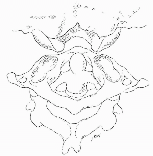 Figure 3.1. Dorsal view of the occipitoatlantal articulation. The occipitoatlantal articulation has been rotated forward to allow visualization of the articulation between the base of the skull and the saddle-type surface of the axis. |
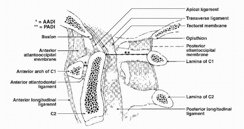 Figure 3.2. Midsagittal section through the upper cervical spine. |
ATLANTOAXIAL JUNCTION
The atlantoaxial (C1-C2) complex is composed of two facet joints and the unique atlantodental articulation. Stability at this highly mobile junction is primarily dependent on ligamentous structures. Sagittal plane motion (flexion-extension) in C1-C2 has been reported by several authors to be on average 11 degrees and may be facilitated by a rounded tip of the dens (8,13,21). Rotation in the upper cervical spine represents 60% of the entire cervical spine rotation and has been reported to be between 39 degrees (21) and 47 degrees (13) on each side. Lateral bending is negligible (13,22).
The IAR for sagittal plane motion is located in the region of the middle third of the dens, and for axial rotation it is located in the central axis of the dens (13). Dorsal translation is prevented by mechanical abutment of the dorsal aspect of the ventral ring of C1 on the dens. Ventral translation is prevented primarily by the transverse ligament (Fig. 3.4). The paired alar ligaments, through their ventral atlantodental component, provide secondary restraint (5,15). The accessory atlantoaxial ligaments and capsular ligaments are tertiary stabilizers. Up to 3 mm of ventral translation of C1 on C2, as measured at the anterior atlantodental interval (AADI), is normal (Fig. 3.2). Fielding and others noted that for this interval to increase, the transverse ligament must be attenuated (23). As the AADI increases to 5 mm or greater, the transverse ligament and accessory stabilizing ligaments have been ruptured. As the AADI increases, the space available for the spinal cord decreases. In conditions such as rheumatoid arthritis, increases in the AADI can lead to cord compression and myelopathy. The transverse ligament also protects the atlantoaxial joint from a rotary dislocation. With the transverse ligament intact, a complete bilateral dislocation can occur at 65 degrees of rotation. With transverse ligament disruption, dislocation can occur at 45 degrees of rotation.
Finally, the paired alar ligaments also restrict rotary motion, since sectioning of one ligament will increase contralateral rotation (5,15,17, 18 and 19).
Finally, the paired alar ligaments also restrict rotary motion, since sectioning of one ligament will increase contralateral rotation (5,15,17, 18 and 19).
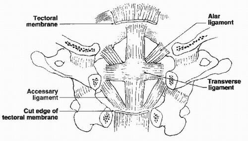 Figure 3.3. Dorsal view of the upper cervical spine. The lamina of C1 and C2, as well as the spinal cord, has been removed to allow visualization of the ligamentous structures. |
As with the C0-C1 junction, distraction and compressive motion at the C1-C2 junction is indicative of an underlying pathologic process. Compression is limited by the lateral mass articulation of the C1-C2 joints. Unstable atlas ring fractures with disruption of the transverse ligament and erosive conditions of the lateral mass articulations can render the C1 ring incompetent to compressive loads and result in atlantoaxial impaction (otherwise known as basilar invagination or cranial settling). The tectorial membrane and posterior atlantooccipital membrane limit distraction at the C1-C2 junction.
LOWER CERVICAL SPINE
The middle and lower cervical spine segments have similar anatomic and functional characteristics; their motion can be represented by the functional spinal unit (FSU). The FSU is defined as the smallest segment of the spine that exhibits biomechanical characteristics similar to those of the entire spine. It is composed of two vertebrae, the intervertebral disk, and associated ligamentous and capsular structures (Fig. 3.5).
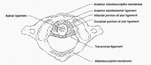 Figure 3.4. Axial view of the axis from the occiput-C1 joint. |
Compression of the lower cervical spine is resisted by the intervertebral disk, vertebral body, and, depending on the position of the spine, the facet joints. The C3 through C6 vertebral bodies have a concave upper and a convex lower surface. The lateral projections of the upper endplate are called uncus (“hook”) and form the uncovertebral joints (joints of Luschka) with the corresponding convex lateral surface of the lower endplate of the superior vertebra. These joints support part of the axial load after disk degeneration.
The average vertebral body size increases from C2 to C7, with width ranging from 15.6 to 23.4 mm and depth ranging from 15.6 to 18.1 mm. The average pedicle height is 7 mm, and the average width is 5 to 6 mm. The angle made by the pedicle in the axial plane decreases from 40 degrees in C3 to 29 degrees in C7 (24). The laminae
project dorsomedially from the pedicles and form the spinous process in the midline, and the facets laterally. The articular surfaces of the facets are inclined approximately 45 degrees from the horizontal plane and get steeper in the lower segments. The motion segments are connected and stabilized by the intervertebral disk, the ligaments, and the facet capsules.
project dorsomedially from the pedicles and form the spinous process in the midline, and the facets laterally. The articular surfaces of the facets are inclined approximately 45 degrees from the horizontal plane and get steeper in the lower segments. The motion segments are connected and stabilized by the intervertebral disk, the ligaments, and the facet capsules.
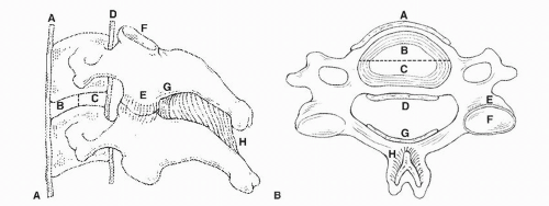 Figure 3.5. Lateral (A) and axial (B) views of an FSU of the middle and lower cervical spine. The important anatomic structures are as follows: ALL (A), ventral disk and annulus (B), dorsal disk and annulus (C), PLL (D), facet capsules (E), facet joints (F), ligamentum flavum (G), and interspinous ligament (H). |
INTERVERTEBRAL DISK
Compressive forces are transferred through the intervertebral disk, the vertebral body, and the facet joints. The intervertebral disk is a viscoelastic material, and its mechanical properties are dependent on the rate of loading. At low load rates, the disk deforms and is more flexible, but at higher rates the disk becomes stiff (2). The disk responds to loading by dehydrating and getting stiffer until a new equilibrium is reached. When the applied stress is reduced, the disk rehydrates accordingly (25). The disk is the major compressive component of the spine, and the ability to tolerate vertical loading in excess of the failure point of the vertebral body is well documented (26,27). The tensile properties of the disk annulus are related to the orientation of the collagen fibers. The annulus fibrosus is stronger in a direction 15 degrees from horizontal and weakest along the disk axis (28). The intervertebral disk also provides some torsional stability (29). Degeneration and dehydration of the disk affect the viscoelastic characteristics (creep and relaxation). A degenerated disk deforms more and faster than a healthy disk, applying greater load to the periphery of the endplate through the annulus.
VERTEBRAL BODY
There is an obvious trend toward increased compression strength from upper cervical levels to lower lumbar levels. The basic average value of 1,700 N comes from the classic work of Messerer (30). A similar value of 1,570 N was found in various studies of vertical impact loading with cadavers (31). Bell et al. (1) have shown that a 25% decrease in osseous tissue results in a more than 50% decrease in the strength of a vertebral body. In general, vertebral body strength decreases with age and osteoporosis (32).
The rate of load application (fast or slow) is an important factor in determining the type of fracture. Fast loading rates produce burst-type fractures with gross displacement, whereas slow loading rates produce wedgeshaped fractures. After a fast-loading-rate impact injury (burst fracture), the spine recoils, and the residual canal encroachment can be significantly less than the maximum during impact (33).
FACET JOINTS
The facet joints aid variably in resisting compressive loads in the spine with more load resisted in extension than flexion. The superior articular facets of C2 to C4 face dorsomedially and are circular or oval. From T1 and lower, the facets face dorsolaterally and have a more transverse orientation. The transition between C4 and T1 can be gradual or sudden. The most frequent site of the transition is at the C5-C6 segment (34).
Zdeblick et al. (3,4) studied the role of the facet capsules and joints in resisting flexion. In a nondestructive flexion test, dorsal displacement increased 4% after a 25% bilateral capsule resection, 5% after a 50% resection, 32% after a 75% resection, and 22% after complete resection. Flexion-moment testing revealed no significant difference between intact specimens and those treated by laminectomy or by laminectomy with 25% bilateral partial facetectomy. A 50% facetectomy resulted in a 2.5% increase in dorsal strain, and 75% or 100% facetectomy resulted in a 25% increase in dorsal strain compared with normal.
Zdeblick et al. (3,4) have also described the contribution of the facet joints and capsules to torsional stability.
Although no gross subluxation was seen, torsional displacement increased 1% after 25% capsular resection, 19% after 50% resection, and 25% after 75% or 100% resection. After 75% and 100% facetectomy, torsional stiffness decreased significantly to 57% and 49% of normal, respectively. The facet capsule is an important stabilizer in acceleration injuries of the cervical spine (35,36).
Although no gross subluxation was seen, torsional displacement increased 1% after 25% capsular resection, 19% after 50% resection, and 25% after 75% or 100% resection. After 75% and 100% facetectomy, torsional stiffness decreased significantly to 57% and 49% of normal, respectively. The facet capsule is an important stabilizer in acceleration injuries of the cervical spine (35,36).
UNCINATE PROCESSES AND UNCOVERTEBRAL JOINTS
Related posts:
 Cervical Orthoses and Cranioskeletal Traction
Cervical Radiculopathy: Diagnosis and Differential Diagnosis
Computed Tomography and Myelography of the Cervical Spine
Embryology of the Craniovertebral Junction and Congenital Malformations in the Region
The Use of Cervical Orthoses, Halo Devices, and Traction in Children
Subaxial Cervical Injuries: Current Concepts in Classification and Treatment
Cervical Orthoses and Cranioskeletal Traction
Cervical Radiculopathy: Diagnosis and Differential Diagnosis
Computed Tomography and Myelography of the Cervical Spine
Embryology of the Craniovertebral Junction and Congenital Malformations in the Region
The Use of Cervical Orthoses, Halo Devices, and Traction in Children
Subaxial Cervical Injuries: Current Concepts in Classification and Treatment
Stay updated, free articles. Join our Telegram channel

Full access? Get Clinical Tree


