Magnetic Resonance Imaging of the Cervical Spine and Spinal Cord
Christopher G. Ullrich
Magnetic resonance imaging (MRI) is based on the physical phenomenon of nuclear magnetic resonance (NMR). Physicists Edward M. Purcell of Harvard University and Felix Bloch of Stanford University independently described NMR in 1946 and received the 1952 Nobel Prize for this achievement. Since then, NMR spectroscopy has become a powerful analytic technique for studying the chemistry and physical structure of molecules. Attempts to apply NMR techniques to medical imaging began around 1970. Working at the State University of New York (SUNY) Downstate Medical Center, Raymond Damadian’s research team produced the first whole-body human image on July 3, 1977. Images of much smaller objects had previously been obtained by Damadian and by other research groups, including Paul Lauterbur at SUNY Stony Brook and Peter Mansfield, Waldo Hinshaw, and E. Raymond Andrews at the University of Nottingham. Although crude, Damadian’s image demonstrated that a powerful medical imaging device was possible. Intense commercial development followed, with the first Food and Drug Administration (FDA) market approvals for MRI devices granted in 1984. MRI technology continues to rapidly evolve.
This chapter briefly reviews the technical concepts related to MRI. The characteristic appearance of these images is described, and specific clinical applications in the cervical spine and spinal cord are illustrated. The relationship between MRI and computed tomography (CT) of the cervical spine is a focus of this chapter. Finally, speculation is made concerning future development and medical applications of MRI.
PHYSICS OF NUCLEAR MAGNETIC RESONANCE
Although a detailed physics explanation of NMR is well beyond the scope of this chapter, a basic understanding of the underlying physical phenomenon involved in NMR is essential to understanding MRI. Simply stated, atoms whose nuclei contain an odd number of protons and neutrons resemble a continually spinning top and behave as a small bar magnet. In nature, these atoms are randomly aligned and no magnetic forces are apparent. When an external magnetic field is applied, its force tends to align the magnetic poles of the spinning nuclei. Most of the nuclei will be in a low-energy state, in alignment with the external magnetic field. High-energy nuclei align themselves against the external magnetic field.
The spinning nuclei precess (wobble) around the vector of the external magnetic field, resembling wobbling tops. Each nucleus precesses at its own specific frequency, called the Larmor or resonant frequency, and is determined by the strength of the “bar magnet” of the nucleus and the externally applied magnetic field. If a radio wave at the exact resonant frequency is beamed at right angles to the magnetic field, some low-energy nuclei will absorb energy, undergo a “spin flip,” and convert to the high-energy state. This absorbed energy is emitted at the same radio frequency when the nucleus returns to the low-energy state. This characteristic absorption and release of specific radio frequencies is descriptively termed NMR.
The character of the high-energy nucleus can also be described by the time it takes to return to the low-energy state. The spin-lattice relaxation time T1 is determined by the interaction between the nucleus and its environment (lattice). The spin-spin relaxation time T2 describes the interaction between adjacent nuclei. Therefore, the same high-energy nucleus will emit its characteristic radio signal at different times depending on what surrounds it. These properties (resonant frequency, T1, and T2) form the basis of NMR spectroscopy and make it a powerful technique for analyzing molecules and their environment.
MAGNETIC RESONANCE IMAGING
The terms NMRI and MRI are equivalent, but the latter term is preferred in the diagnostic radiology literature because of the prevalent public phobia about anything identified as “nuclear” and also to distinguish this method from nuclear medicine techniques involving radioactive isotopes.
Magnetic field strength is measured in tesla (T) units. MRI devices are broadly categorized as low field (<0.3 T), midfield (0.3 to 0.9 T), and high field (1.0 T or greater). The MRI devices that are 3.0 T are the highest field strength currently approved by the FDA. A superconducting magnet is used most commonly in midfield and highfield systems. These devices produce an extremely uniform magnetic field, a highly desirable feature. They are costly to build and operate. These high-field MRI systems can support the high-power gradients and radio frequency switching speeds necessary to implement rapid imaging sequences, including echo planar MRI and MR spectroscopy (MRS). They can reliably perform the thin-section imaging needed for excellent MRI of the cervical spine. The MRIs used to illustrate this chapter were produced with 1.5-T MRI systems.
MRI systems are developing along several pathways. Open-design MRI systems using superconducting magnets with field strengths of 0.7 to 1.2 T have become available. These units can produce adequate thin-section images that are essential for good-quality cervical spine studies. The maximum field of view is usually limited to no more than 40 cm, which can make total spine examinations tedious. New 1.5-T MRI systems using short-bore magnet designs seem less confining to patients than the older magnet designs. Improved coil and gradient design along with sophisticated pulse sequences are further improving image quality and reducing examination times. 3.0-T MRI systems can deliver higher-resolution images or more rapid image acquisition times when compared with a 1.5 T MRI. Pulsation, magnetic susceptibility, and chemical shift image artifacts are significant technical challenges to good cervical spine imaging at 3.0 T. Resistive magnets, used in low-field systems, produce a less stable magnetic field. Permanent magnets, used in low-field or midfield systems, produce a stable magnetic field. Magnetic field uniformity comparable to that of superconducting magnets is difficult to achieve with either permanent or resistive magnet designs. These magnets are used primarily in low-cost imagers because the magnets are less expensive to manufacture, site, and maintain. They are also adaptable to wide-aperture or open-imager designs. The primary limitations of these low-field systems for cervical spine imaging are their common inability to perform thin (2-mm) images and their long data-acquisition times. Regardless of the magnet or magnetic field strength used, diagnostic cervical spine images can be obtained if proper imaging techniques are used.
The NMR instrument obtains its signal from the entire sample volume. To mathematically reconstruct an image, the MRI signal must be localized within the object being imaged. This localization is usually obtained using a gradient technique. A gradient is a small secondary magnetic field that has a known variable strength. Magnetic field strength influences the exact resonant frequency. With a gradient applied, the slightly different radio frequencies detected determine where the signal arises. This information, in combination with the shape and orientation of the radio frequency pulse, determines the precise location of the signal and permits mathematical image reconstruction. Most machines use two-dimensional (2-D) Fourier transformation mathematics to calculate the MRI from the detected signal in a manner similar to radiographic CT.
Two time variables describe how the machine functions and determine the nature of the image obtained. The repetition time interval between radio frequency input pulses is termed TR. After the input pulse, the time at which the echo (emitted resonant radio frequency signal) is detected is termed TE. These time values are expressed in milliseconds.
At present, virtually all clinical MRI is performed using the hydrogen nuclei signal (proton imaging). Hydrogen, as a constituent of water, is the most abundant resonant nucleus in soft tissues and therefore provides the strongest signal. Other nuclei, such as sodium and phosphorus, may be imaged using high-field-strength systems, but the image quality is low owing to the weak signals obtained. Well-described practical clinical applications for these additional nuclei remain to be developed.
The methods for acquiring MRI data are termed pulse sequences. Spin echo (SE), inversion recovery (IR), gradient echo (GRE), and fast or turbo spin echo (FSE) are some of the techniques used. SE pulse sequences are described by TR and TE values. By varying these factors, different tissue-contrast relationships are obtained (Fig. 25.1). If a short TR/TE technique (e.g., SE = 500/30) is used, the image is termed T1 weighted because most of the detected echo signals reflect the T1-governed nuclear interactions (spin lattice). The resulting image shows a low signal from cortical bone owing to a paucity of water molecules. The cerebrospinal fluid (CSF) is hypointense, relative to muscle and spinal cord, because of its short T1 value. Fat has an increased signal relative to the spinal cord, whereas most lesions are either low or isointense compared with the spinal cord (Fig. 25.2). These T1-weighted images tend to have the best spatial resolution because the strongest signal is obtained with such pulse sequences.
Long TR/TE techniques (e.g., SE = 2,500/120) are termed T2-weighted images because most of the detected signal is determined by the T2 (spin-spin) interactions of the nuclei. The emitted signal resulting from T1-governed events has already dissipated. The term T2*-weighted is used for GRE images because GRE T2 values differ somewhat from SE T2 values. The CSF now demonstrates greater intensity than the spinal cord, producing the socalled pseudomyelogram effect. The bone signal remains quite low compared with the spinal cord, whereas fat continues to show an increased signal. Pathologic processes tend to show an increased signal compared with the spinal cord because in most cases, they are associated with increased tissue water (Fig. 25.1). Small lesions lying in the spinal fluid or adjacent to it can be obscured when both the spinal fluid and the lesion demonstrate an increased signal.
Images produced using long-TR and short-TE technique (e.g., SE = 2,500/30) are termed balanced because relatively equal contributions of T1- and T2-governed echoes are involved. In the cervical spine, this technique may allow pathologic processes to have a high signal while the spinal fluid remains isointense or hypointense relative to the spinal cord. Lesions that may be masked on a more heavily T2-weighted image might now be apparent.
Gadolinium compounds can be used for intravenous (IV) enhancement in MRI in a manner similar to the use of iodine contrast agents for CT. Gadolinium shortens T1 relaxation time, producing a brighter T1 signal. It has little impact on T2-weighted images and does not cross
the intact blood-cord barrier. It will accumulate in areas of infection, inflammation, and tumors (Fig. 25.3), making these sites more conspicuous on T1-weighted images. Unlike iodine IV contrast for CT, it is relatively ineffective as an agent for arterial opacification because of both the small volume of injection and its rapid clearance from the bloodstream. Veins often show some “brightening.” Injected gadolinium contrast is generally well tolerated; allergic reactions are rare. Because of issues of cost and time, gadolinium is used selectively when an appropriate clinical diagnosis is considered.
the intact blood-cord barrier. It will accumulate in areas of infection, inflammation, and tumors (Fig. 25.3), making these sites more conspicuous on T1-weighted images. Unlike iodine IV contrast for CT, it is relatively ineffective as an agent for arterial opacification because of both the small volume of injection and its rapid clearance from the bloodstream. Veins often show some “brightening.” Injected gadolinium contrast is generally well tolerated; allergic reactions are rare. Because of issues of cost and time, gadolinium is used selectively when an appropriate clinical diagnosis is considered.
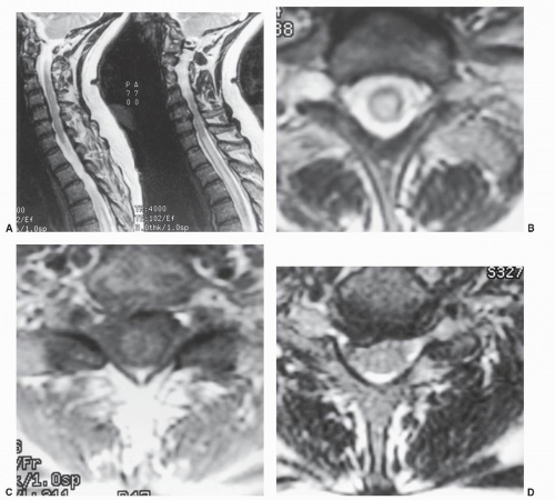 Figure 25.1. This 56-year-old woman suddenly developed weakness in both legs 1 week after the onset of a flu-like illness. A: A pair of sagittal T2-weighted FSE images depict an enlarged spinal cord with extensive increased T2 signal extending from the C7-T1 to the T6 vertebral level. B: An axial T2-weighted FSE MRI made at the first thoracic vertebral level confirms a diffuse central increased T2 signal within an enlarged spinal cord. Some sparing of the peripheral white matter is noted. C: An axial T1-weighted SE MRI made at the first thoracic vertebral level shows no evidence of a syrinx or abnormal gadolinium enhancement. MRI is superior to other imaging techniques for showing intrinsic spinal cord lesions. A presumptive diagnosis of viral myelitis was made. The patient gradually improved with medical therapy. D: An axial T1-weighted SE MRI made at the C6-C7 level shows an asymptomatic right C6-C7 herniated disk. The lesion is also seen on the sagittal T2-weighted MRI (A). |
Normal fat produces a relatively bright signal on both T1- and T2-weighted images, which can obscure gadolinium enhancement on T1-weighted images and abnormal T2 signal on T2-weighted images. This bright fat signal can be reduced or eliminated by adding a fat-suppression pulse
to the standard SE pulse sequence; IR pulse sequences also produce fat suppression. IR images resemble fatsuppressed T2-weighted SE images and are quite useful in patients with trauma (Fig. 25.4), infection, or bony metastases. Most centers use these fat-suppressed images electively in the appropriate clinical setting.
to the standard SE pulse sequence; IR pulse sequences also produce fat suppression. IR images resemble fatsuppressed T2-weighted SE images and are quite useful in patients with trauma (Fig. 25.4), infection, or bony metastases. Most centers use these fat-suppressed images electively in the appropriate clinical setting.
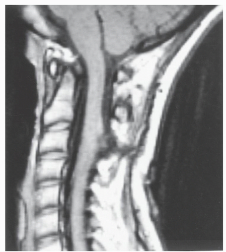 Figure 25.2. This 16-year-old girl had vague neck pain complaints and a cutaneous dimple on the dorsal neck. The sagittal T1-weighted SE image shows a tract from the dorsal neck into the spinal canal at C3. The spinal cord is expanded, and epithelial tissue is visible along the dorsal aspect of the spinal cord. MRI is the procedure of choice for the initial evaluation, but it does not demonstrate the associated dorsal bony dysraphism well. The radiographic diagnosis of dorsal dermal sinus with epidermoid tumor in the spinal cord was confirmed at surgery. |
Data acquisition in MRI is usually performed with a 2-D technique in which multiple adjacent images are obtained simultaneously. A small gap is often present between these successive images. Direct axial, coronal, and sagittal image planes are produced without moving the patient, but separate data acquisitions must be performed for each image plane. It is often possible to obtain two or more TE values simultaneously (so-called dual or multiecho techniques), particularly when a long TR is employed in the pulse sequence.
Volume imaging techniques are also feasible. Unlike 2-D image methods, in which each image is separately encoded, volume techniques encode the entire imaging area as one seamless data set. Once obtained, any desired image plane can be extracted from the volume data set, thus eliminating separate data acquisitions. Volume data sets are ideal for three-dimensional (3-D) image processing. Two types of volume data acquisitions are possible. Isotropic acquisitions take longest to perform but produce equal resolution in all three orthogonal imaging planes (axial, coronal, and sagittal). Anisotropic acquisitions are quicker and therefore more commonly used. The primary imaging plane will have the best spatial resolution; the two other orthogonal planes will have somewhat reduced spatial resolution. Volume acquisitions using conventional SE pulse sequences take 20 minutes or longer and are not practical. GRE anisotropic volume acquisitions, which take less than 6 minutes, are commonly used to obtain thinsection axial MRIs of the cervical spine. Two-millimeterthick T2-weighted axial images with no spatial gaps can be obtained from the C2 to T1 vertebral levels in one acquisition. Interleaved 2-D image acquisition techniques can eliminate the spatial gaps between images but double the image acquisition time.
A variety of different imaging coils are used for MRI. These coils are antennas that detect the emitted resonance signal. Optimized coil design has a real impact on the quality of the image obtained. The head coil is designed for imaging the brain. It usually can produce high-quality images of the foramen magnum and cervical spine down to the C2-C3 level. Most MRI systems have a surface coil that is designed for spinal imaging. These coils allow the entire cervical spine to be examined at high resolution in a single field of view. Phased-array coils are multiple-surface coils that can be operated together to obtain better image quality over a larger field of view (Fig. 25.5). The MRI body coils are designed for thoracic and abdominal imaging and usually provide poor images of the spine and spinal cord; generally speaking, they should not be used for cervical spine examinations.
Many other technical factors contribute to better quality in cervical spine MRI examinations. Properly placed saturation pulses can reduce imaging artifacts related to physiologic motion. Cardiac gating is sometimes helpful. The direction of phase and frequency encoding gradients can be important in reducing image artifacts. Physiologic motion and magnetic susceptibility artifacts remain significant challenges for MRI of the cervical spine and spinal cord. A detailed examination of these factors is beyond the scope of this chapter. Also beyond the scope of this chapter are physics discussions of many other advanced MRI techniques, such as MR angiography (MRA) without or with gadolinium enhancement, echoplanar MRI, CSF flow measurements using magnitude or phase contrast encoding, perfusion and diffusion MRI, time-resolved imaging, cortical activation functional MRI (fMRI), and MRS. So too are image processing techniques such as ray and maximum-intensity projection imaging, image segmentation, multimodality image fusion, volumetric 3D visualization and model manufacturing, and image-guided surgery and simulation.
In summary, MRI is performed by placing the patient in an external uniform and stable magnetic field. A radio frequency pulse is beamed into the patient to induce the NMR phenomenon. A receiver coil detects the emitted radio frequency as the nuclei revert to a low-energy state within the magnetic field. Gradients produce slight local variations in the strength of the magnetic field and permit spatial localization of the emitted resonant frequency. This detected signal is mathematically processed to produce the actual MRI. By varying TR and TE factors, SE images that are T1 or T2 weighted are produced. The T1 images have the best spatial resolution; T2 images tend to accentuate pathology.
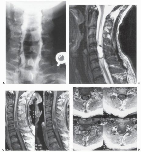 Figure 25.3. This 33-year-old man presented with a clinical history and findings of slowly progressive cervical myelopathy. A: An anteroposterior myelogram shows an expansile intra-axial lesion at the C5-C6 levels. Myelography is unable to classify this abnormality further. B: A midsagittal T2-weighted FSE image confirms a well-defined intra-axial lesion at C5-C6. It has very high T2 signal, with focal areas of low signal along the margin. Increased T2 signal extends above and below the lesion, consistent with spinal cord edema. C: Two adjacent post-gadolinium-enhanced sagittal T1-weighted SE MRIs. D: Four consecutive post-gadolinium-enhanced axial T1-weighted SE MRIs at C5-C6 show a low-T1-signal central cyst with faint enhancement along most of the cyst wall. A focal enhancing nodule in the cyst wall is noted inferiorly and to the right. The radiographic diagnosis of hemangioblastoma was surgically confirmed. For examining the spinal cord, MRI is superior to all other imaging techniques. |
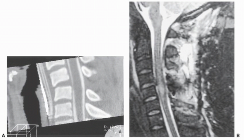 Figure 25.4. This 35-year-old woman suffered a C4-C5 fracture with quadriplegia in a motor vehicle accident. A: A midsagittal 2-D CT reconstruction image made from a primary CT myelogram performed the day of the accident. The spinal cord is enlarged at C5, consistent with a contusion. There is no internal detail of the spinal cord by CT. The spinal cord is not mechanically compressed. The dorsal aspect of the C4-C5 disk space is distracted, but no effacement of the intrathecal contrast behind the C4-C5 disk space is seen. A kyphotic deformity centered at C4-C5 is noted. The interspinous process distance at C4-C5 is widened, indicating ligamentous disruption. B: A midsagittal IR MRI made 5 days after the CT examination. The kyphotic deformity seen in A has been reduced. A small disk herniation now projects into the spinal canal that was not seen in A. The migration of the C4-C5 disk fragment presumably occurred in association with the fracture-dislocation reduction. Neither the C4-C5 disk herniation nor a small hematoma behind the C4 vertebral body is significantly compressing the spinal cord. The spinal cord contusion, along with extensive dorsal paraspinal soft tissue injuries, is now directly visualized by MRI. Migrating disk fragments associated with fracture reduction on rare occasions have produced spinal cord compression and significant new neurologic deficits. These disk fragments and epidural blood can be seen with high-resolution CT, but they often have similar CT densities. On MRI, as in this case, the blood and disk fragments often have slightly different signal characteristics. |
ADVANTAGES AND LIMITATIONS OF MAGNETIC RESONANCE IMAGING
MRI involves the use of nonionizing radiation and is considered biologically safe by current testing standards. No known deleterious effects are produced in a normal subject. Because of its excellent spatial and contrast resolution, MRI exhibits high lesion sensitivity. By skillful use of the many available pulse sequences, normal and diseased tissues can be identified and characterized accurately; IV gadolinium contrast agents also assist in this process. Gadolinium is well tolerated by patients; anaphylactic reactions are rare. With the patient supine, MRI allows direct sagittal, coronal, axial, and oblique images to be obtained. Volume-acquisition imaging techniques are feasible as well. With high-field MRI systems, patient examination times of 30 minutes or less are common. These capabilities have made MRI a major modality for the evaluation of the cervical spine.
Not all patients can be examined successfully by MRI. Patients with cardiac pacemakers or implanted defibrillators should not be examined because the magnetic field will disrupt operation of these devices. A variety of medical implants are potentially incompatible with safe MRI examinations, including some heart valves, lens implants, cochlear implants, infusion pumps, and older cerebral aneurysm clips. Patients with medical implants (e.g., orthopaedic rods and plates, joint prostheses, and permanent dental work) can be safely examined. Usually there is a loss of image detail around the site of these materials as a result of distortion of the local magnetic field. The remainder of the image often looks unaffected, but subtle image distortion and artifacts may be present, which can affect the perceived diagnosis. If the area of interest is adjacent to metal, MRI is probably not going to be clinically satisfactory. Patients should be questioned carefully about metal and medical devices in the body before MRI examinations
are done. MRI centers maintain lists of devices that can pose problems. If necessary, the medical-device manufacturer can be contacted for advice before MRI. Occasionally, a patient must be disqualified for MRI because of traumatically acquired metal in the body.
are done. MRI centers maintain lists of devices that can pose problems. If necessary, the medical-device manufacturer can be contacted for advice before MRI. Occasionally, a patient must be disqualified for MRI because of traumatically acquired metal in the body.
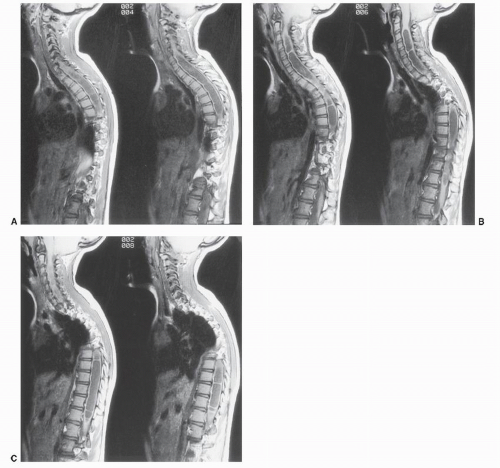 Figure 25.5. An 8-year-old girl with a levoscoliosis of the dorsal spine. A-C: Six consecutive sagittal T1-weighted SE images made from left to right demonstrate a multiseptated syrinx extending from C2-C3 to the conus. A Chiari II malformation with a large quantity of cerebellar tissue at C1 is present, best seen in B. A previously performed dorsal C1 and occipital decompression surgery has relieved the mechanical compression of the cervicomedullary junction, but the associated syrinx persists. Simultaneous examination of the cervical and thoracic spine was accomplished with phasedarray MRI coils
Related posts:Stay updated, free articles. Join our Telegram channel
Full access? Get Clinical Tree
 Get Clinical Tree app for offline access

|


