Chapter 30 Percutaneous Pedicle Screw Fixation
Anterior lumbar interbody fusion (ALIF) has advantages over other fusion procedures, such as shorter operating time, lower blood loss, and no epidural complications [1–6]. However, in the case of spondylolytic or degenerative spondylolisthesis at multiple vertebral levels, higher pseudarthrosis rates have been reported with ALIF [7,8].
Percutaneous pedicle screw fixation (PPF) was developed as a minimally invasive posterior augmentation for ALIF [9]. At present, the PPF technique has been applied to a wide range of fusion procedures, including mini–open transforaminal lumbar interbody fusion (TLIF) [10].


Preoperative preparation
 Computed tomography is used to ascertain the size of the pedicle and to plan the length and direction of the screw (Fig. 30-1).
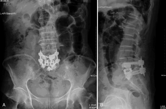
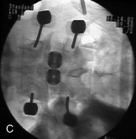
 For older women, a bone density study helps determine whether the bone mineral content is adequate for pedicle screw fixation. In patients with severe osteoporosis, vertebral augmentation by vertebroplasty is needed (Fig. 30-2).
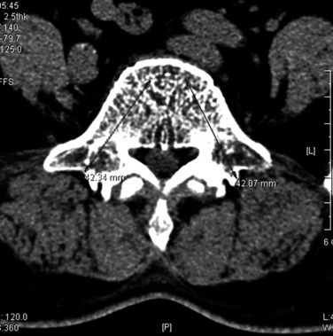
Procedures
Procedure for Percutaneous Pedicle Screw in General
2. The patient is placed in a prone position with the abdomen free. The procedure is performed under C-arm (fluoroscopic) guidance.
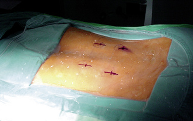
4. With a No. 11 scalpel blade, the surgeon makes a 15-mm-long incision for each screw over the spinous process at the level to be fused (Fig. 30-3).
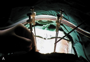
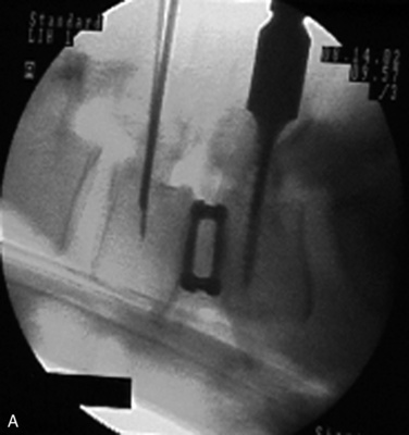
5. A 14-gauge vertebroplasty needle is positioned with its tip on the lateral margin of the pedicle oval and advanced until the stylet tip has abutted the bone under anteroposterior view (Fig. 30-4).
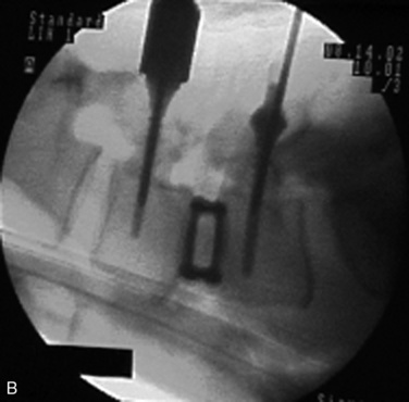
6. The surgeon advances the needle through the cortex by tapping its back end with a mallet on a lateral fluoroscopic view. The lateral view shows the needle passing parallel to the superior and inferior edges of the pedicle. With the needle tip located on the posterior vertebral bodyline on a lateral view, the intrapedicular location of the needle is confirmed on the anteroposterior view (Fig. 30-5).
7. After confirmation of placement, the needle is advanced so its tip is at the junction of the middle and posterior thirds of the vertebral body.
8. The stylet is replaced by a 200-mm-long Kirschner wire, and then a series of sequential dilations is performed along the Kirschner wire.
9. With the Kirschner wire still in place, a hole is drilled in the pedicle with a 5.0-mm cannulated drill bit.
10. After removing the Kirschner wire, the surgeon places a long straight beaded-tip probe into the pedicle and evaluates the pedicle walls are for possible perforation.
11. The surgeon inserts a pedicle screw into the prepared hole using the same orientation as for the Kirschner wire and under fluoroscopic guidance.
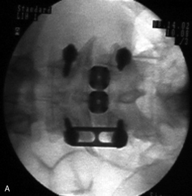
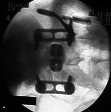
13. The surgeon makes a soft tissue tunnel that connects the two pedicle screw heads in a each side is made using a custom-made curved passer through the same stab wound and muscle layer (Fig. 30-6).
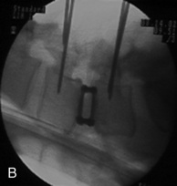
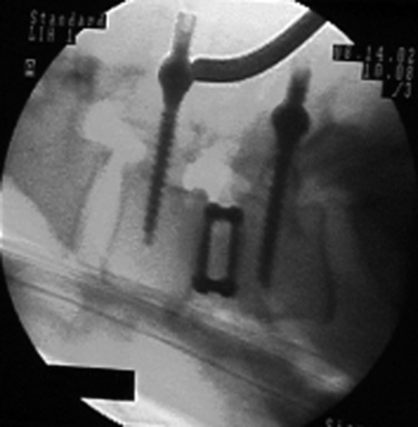
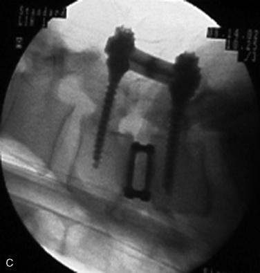
14. Then the surgeon inserts a longitudinal connector (rod or plate) and passes it firmly through both screw heads (Fig. 30-7).
15. Fluoroscopic confirmation of the connector passage through the screw heads is obtained in both planes to ensure proper positioning of the connector.
16. A locking bolt is introduced into the screw head through the same stab wound and is tightened under fluoroscopic guidance or direct vision with brief retraction of the stab wound. While tightening a screw-connector construct, the surgeon uses the remaining screw path to give anti-torque and some compression force.
17. The same procedure is performed on the contralateral side of the spine, after which all incisions are irrigated and closed.
Related posts:


Stay updated, free articles. Join our Telegram channel

Full access? Get Clinical Tree


