Chapter 31 Posterior Minimally Invasive Procedures to Spine Tumors
VERTEBROPLASTY TECHNIQUE
TRANSPEDICULAR APPROACH
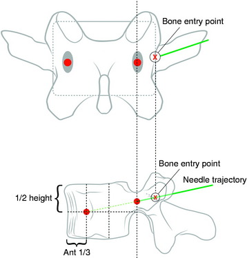
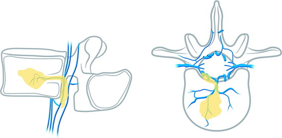
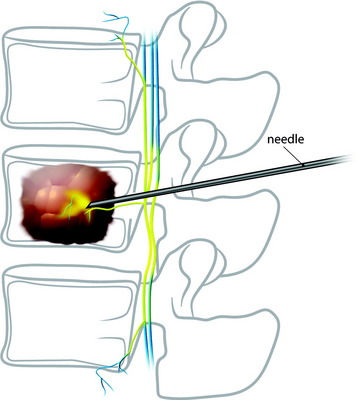
Under fluoroscopic assessment, a 10- to 15-gauge 10- to 15-cm length needle, preferentially with a beveled cutting tip, is inserted along the selected pedicle (Fig. 31-1).1 Within the pedicle, the bevel of the needle is oriented medially (the tip of the needle pointing laterally) to avoid the spinal canal. Once within the vertebral body, the bevel is rotated to face laterally (the tip of the needle pointing medially), directing the needle medially, toward the midline. The most desirable position of the needle tip is the anterior third of the vertebral body near the anteroposterior midline (Fig. 31-2). When dealing with a vertebra plana, a more lateral position of the needle is desired. If the underlying pathological condition remains uncertain before the cement injection, a bone biopsy specimen can be obtained using a 15- to 18-gauge biopsy needle placed through the vertebroplasty (VP) needle. Then vertebral venography is performed to evaluate the flow dynamics. When a high-flow, hypervascular pattern is observed, the reposition of the needle tip may be required to perform an embolization of the venous channels, either with alcohol, N-butyl-2-cyanoacrylate (Histoacryl), Gelfoam, plugs, or Avitene powder before cement injection. After the powder and a liquid component are mixed and the desired consistency is reached, the polymethyl methacrylate (PMMA) is injected through the needle. The injection is continued until resistance is met, or the cement reaches the posterior wall of the vertebral body, or a desired result is achieved. The injection should be stopped if epidural, foraminal, or venous leakage is detected.
VERTEBROPLASTY IN CERVICAL LESIONS
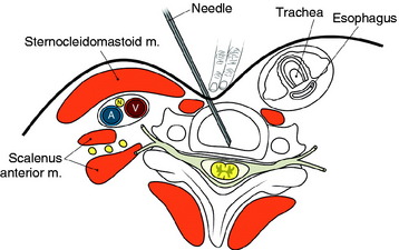
The entry points are along the anterior margin of the sternocleidomastoid (SCM) muscle. With lateral fluoroscopy, the appropriate level and entry height should be determined. After the entry point is marked, a small skin incision is made. The surgeon pushes the medial structures (trachea and esophagus) to the opposite side with index and middle fingers, then applies a firm pressure in the space between the SCM muscle and the trachea, pointing toward the vertebral surface. The needle is then inserted through the space between the trachea and carotid sheath (Fig. 31-3).
CASE ILLUSTRATION
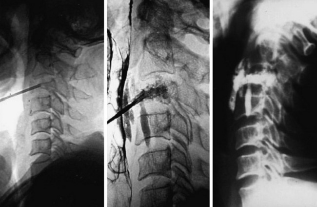
A 45-year-old woman with breast cancer was treated with VP at C3 metastasis (Fig. 31-4). The approach was performed from the left side, with finger compression of the visceral tissue. During VP, esophagography should be performed to check the esophageal injury. Bone cement of 2cc was injected to the compressed C3 body. A small amount of bone cement was seen to leak into the paraspinal space. Preoperative neck pain was much improved after VP.
BIOMECHANICS: VOLUME OF BONE CEMENT
The effective volume of bone cement is estimated to be from 3 to 10cc; however, a study on the effects of bone cement volume and distribution on vertebral stiffness after VP showed that 14% filling or 3.5cc was necessary to restore stiffness of the damaged vertebral body to the pre-damaged value at the lumbar level.2 This result suggests that large fill volume may not be the most biomechanically optimal configuration, and an improvement might be achieved by use of a lower cement volume with symmetrical placement. Also, with the unipedicular approach, the stiffness comparable to the intact body can be achieved in cases of symmetrical distribution of bone cement.
COMPLICATIONS
Pulmonary Embolism
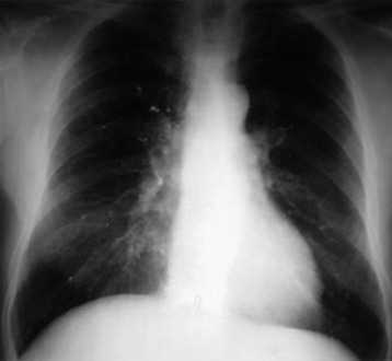
Pulmonary embolism may occur during the VP. Bone cement leaked from the vertebral body via the venous channel can enter the systemic circulation. It may be filtered in the pulmonary circulation system (Fig. 31-5). Even though pulmonary embolism does occur, most patients may be asymptomatic. If symptomatic, patients complain of tachypnea and respiratory difficulty. Tachycardia is monitored. The incidence of pulmonary embolism is 3–4%.3 Most patients can be treated with anticoagulant therapy and respond favorably.4
Neurological Complication (Epidural Leakage)
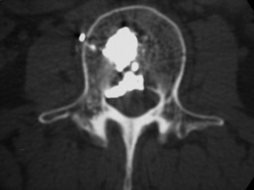
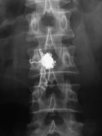
Epidural leakage may occur at a high incidence, up to 50–70% in osteolytic metastasis or myeloma. Most patients with epidural leakage are asymptomatic; however, few patients may undergo surgery because of radiculopathy. Epidural leakage can occur through the fracture line, cortical destruction, the needle track, or the epidural and paravertebral venous plexus (Fig. 31-6).
CASE ILLUSTRATION: EPIDURAL LEAKAGE
A 35-year-old female patient received VP for the treatment of L3 hemangioma. The bone cement leaked through the venous plexus into the epidural space and damaged the right L3 nerve root (Figs. 31-7 and 31-8). The patient suffered from right lateral thigh paresthesia for 6 months. After prolonged treatment with analgesics, the symptom was much improved.
SPECIAL PROBLEMS OF VERTEBROPLASTY IN CANCER PATIENTS
Venogram
The performance of a venogram in a tumor patient is controversial. Unlike with osteoporosis, venogram performed on tumors may result in substantial leakage of contrast into the canal and paravertebral spaces because of significant cortical destruction and bony erosion (Fig. 31-9).
Injection into the Tumor Mass
The injection of the cement into dense tumor mass tissue may be more difficult than in an osteoporotic spine, and the PMMA pattern may appear spotty and discontinuous.5 To provide maximum structural support, both the osteolytic portion of the vertebral body and the seemingly normal bone should be injected. Vascular tumors, such as renal cell cancer metastasis, may show frank arterial flow through the cannula once the stylet is removed. Hence, the trajectory track should be packed with PMMA to prevent excessive bleeding.
PARASPINAL TECHNIQUE: LUMBAR SPINE
Entry Point
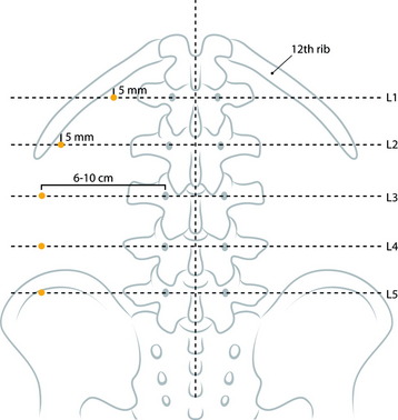
At the upper lumbar spine (L1 and L2), the entry point is just medial to the 12th rib. The midline and a line bisecting the transverse process and pedicle are identified (Fig. 31-10). The entry point is on the bisecting line and is 5mm medial to the 12th rib. The 12th rib is confirmed with fluoroscopy or palpitation of the rib. At lower lumbar spine (L3–5), a line bisecting the transverse process and pedicle is drawn. The entry point is located on the line, approximately 6–10cm away from the pedicle.
Trajectory Angle
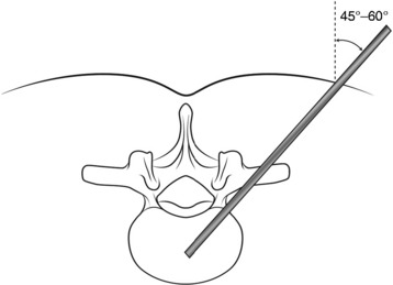
Typical trajectory angles are 45 to 60 degrees as measured from the vertical axis line of the patient (L1: 45–50 degrees, L2: 45–50 degrees, L3: 45–50 degrees, L4: 50–55 degrees, L5: 55–60 degrees) (Fig. 31-11).
Stay updated, free articles. Join our Telegram channel

Full access? Get Clinical Tree


