Normal stable SEPs from the left and right median and left and right posterior tibial nerves. (From UCLA Department of Clinical Neurophysiology, with permission)
SEP IOM is used to provide an alert to the surgeon about potential neurological complications . This is provided in real time so that an intervention could prevent an adverse outcome. SEP IOM also provides the surgeon with a reassurance that surgery is proceeding without complication . This reassurance gives the surgeon confidence to complete a procedure or to be more aggressive with correction, tumor removal, etc., thereby possibly making the surgery more successful. It is important that information (especially alerts) is given to the surgeon in real time. This allows correlation of the alert with surgical steps that may be undone in order to reverse the change.
Stimulation
SEP monitoring techniques
Stimulation |
Lower extremity stimulation sites |
Posterior tibial nerves at the ankle |
Or peroneal nerves at the knee , e.g., in patients with peripheral neuropathy |
Upper extremity stimulation sites |
Median nerves at the wrist for intracranial cases and cervical cases C5 and above |
Ulnar nerves at the wrist for spinal cases at or below C6 |
Stimulus intensity |
Supramaximal (10% over intensity required to record maximal peripheral response) |
Stimulus rate |
5.1 per second per nerve , if tolerated with good peaks |
Or slower if needed to obtain good peaks avoiding harmonics of 60 |
Recording |
For lower extremity stimulations |
Two cortical channels , CPi–CPc and CPz–Fpz |
A cervical channel: CSp5–Fpz |
For upper extremity stimulations |
Two cortical channels, CPc–CPi and CPc–Fpz |
A cervical channel : CSp5–Fpz |
One peripheral channel: Erb’s point ipsilateral, contralateral |
Filters 30 and 3000 Hz, notch filter off, adjusting the filters as needed |
300 trials per EP, more if needed |
Sites
For the lower extremities, electrical stimulation to the PTN is applied to the ankle. That nerve is superficial and located just posterior to the medial malleolus. For some patients, the peroneal nerve is chosen instead. That nerve can be found superficially lateral to the knee, just below the fibular head. That site is useful especially in patients with a peripheral neuropathy, such as diabetics, and in the elderly . Upper extremity stimulation is delivered to the median nerve or ulnar nerve. Both nerves are superficial at the wrist.
Peripheral nerves may be stimulated unilaterally to test left- and right-sided pathways separately. For bilateral monitoring , left and right stimulation can be alternated during the same period of time in a method called asynchronous stimulation . Asynchronous stimulation allows for rapid data collection while still interpreting data with side-to-side specificity . Modern IOM equipment can average simultaneously from several sites using programmable protocols with delays between different stimulation sites.
Bilateral upper and lower SEP monitoring is used for some spine cases. Median or ulnar nerve stimulation is included in thoracic and lumbar cases as a means of monitoring for arm position or anesthesia-related changes . Ischemia secondary to hemodynamic events may also be detected by SEP monitoring from all extremities. Ulnar nerve monitoring also can help detect an incidental brachial plexus impairment resulting from patient positioning during long cases.
For cervical procedures, median or ulnar nerve pathways are the primary pathways monitored. Because the ulnar nerves enter the spinal cord at a lower level, ulnar nerve monitoring is preferred for cervical cases at and below the C6 spinal level. PTN channels also are monitored in cervical cases for detection of a high thoracic or low cervical spinal cord injury . The four limb coverage also provides greater spinal cord protection from events such as hemodynamic changes.
Averaging
SEP data are low amplitude , often <1 μV. This amplitude is less than the surrounding background noise, which includes cerebral EEG activity. To find a reliable SEP measurement, data must be averaged. Averaging of low amplitude signals increases the signal-to-noise ratio (SNR) in a manner proportional to the square root of the number of trials. More trials result in better SNR . About 300 averaged recording trials often produce well-defined peaks.
Intensity
The correct way to determine the optimum stimulus intensity is to determine the intensity that produces the largest amplitude peripheral response and then add 10%. This is known as supramaximal stimulation and ensures that 100% of the nerve fibers are being recruited and that small changes in electrode resistance won’t appreciably affect the recruitment percentage. Supramaximal stimulation will cause a 1–2 cm movement in the appropriate muscle groups in the absence of neuromuscular blockade. Median nerve stimuli produce thumb movement. Ulnar nerve stimuli produce fifth digit movement. PTN stimuli produce foot flexion, while peroneal nerve stimuli produce foot dorsiflexion . A stimulus artifact should be seen at time zero in recording channels, confirming that the stimulus is actually being delivered. Many modern IOM machines show current delivered and returned, and this also can be used to confirm stimulus delivery.
Electrodes
Stimulation electrodes can be needles , disks, or adhesive electrodes. An electrode pair consisting of a cathode and anode is secured over the nerve. The resistance between the electrodes and the skin should be <5 kΩ to ensure adequate stimulus delivery and avoid large stimulation artifact . Needle electrodes provide a low resistance and avoid resistance changes over long cases. For disk or adhesive electrodes, skin preparation with an abrasive is used to reduce electrical impedances . Patients allergic to citrus fruit may have a reaction to the skin preparation gel containing lemon. If using an electrode paste, it should be free of calcium to avoid chemical burns from iontophoresis into the skin.
Rate
The repetition rate must strike a balance between rapid data collection and recording of a quality waveform. Typical repetition rates are between 2 and 5 stimulations per second. A complete data set can usually be obtained in a few minutes at these rates. Repetition rates >5 per second sacrifice data quality for more rapid collection. The amplitude of the peaks will decrease appreciably as rates increase above 5 pulses per second due to refractory times of the individual nerve fibers. Stimulation rates should avoid exact multiples of 60 Hz (or 50 Hz) to avoid line noise artifact.
Recording
Recording bioelectric signals involves optimization of several factors. At the beginning of a case, potentials should be optimized and set as baseline recordings suitable for comparing subsequent data during the procedure. Quality baseline recordings are essential to providing the surgeon with accurate data interpretation. Scouting for optimal baselines includes evaluating different recording sites, filter settings, and other parameters. A simple cookbook one-size-fits-all approach to SEP monitoring often leads to suboptimal recordings. The expertise of the monitoring team is in establishing the best recordings for each patient.
Recording Sites: General Comments
SEP recordings are made from successive sites along the DCML pathway. These recording sites are chosen to provide measurements from peripheral, spinal, subcortical, and cortical levels. In general , the active electrode is placed as near as possible to the anatomic generator, and a reference electrode is placed some distance away. The reference may be another scalp site or a non-cephalic site . Bipolar recording montages compare inputs between two nearby electrodes, while referential recording montages compare inputs between an active electrode near the anatomic generator and a much further placed reference electrode. The amount of electrical noise is proportional to the distance between the active and recording electrode as well as the distance between the anatomic generator and the active electrode. Cervical potentials are more susceptible to electrical noise because of the distance of the generator, yet these potentials are less affected by inhalation anesthetic concentrations due to the lack of synapses up to this point in the pathway. For this reason, they often are included in the recording montage despite their predisposition to noise.
The surgical field may make the preferred recording sites inaccessible. When this happens, it is necessary to scout for alternate recording sites that will yield the highest possible recordings. Neurosurgical craniotomies may displace scalp sites. Cervical surgery may displace cervical recording sites. Several nearby alternate sites may be tried.
Site Nomenclature
The International Federation of Clinical Neurophysiology’s 10–20 System provides the accepted naming convention for scalp recording sites. The 10% extension of the 10–20 system [1] adds additional nomenclature. The EEG chapter in this book has further information on electrode nomenclature. For those unfamiliar with the naming conventions, a brief overview is given here. Electrode sites are named in a coordinate fashion with the first part of the binomial nomenclature indicating the anteroposterior position and the second part of the name indicating mediolateral position. A series of anteroposterior lines are named according to their position relative to certain brain features. The C-line runs generally along the central sulcus. The P-line is at the level of the parietal lobe. The line in between the C-line and P-line is the CP-line. Mediolateral positioning is named relative to the lateral distance from the Z-line which runs along the vertex of the skull (midline). Odd numbers are to the left of the Z-line and even numbers to the right. The smaller the number, the closer to the Z-midline. For example, an electrode placed over the right postcentral gyrus near the hand area (lateral) would be CP4. The midline position would be named CPz. The location halfway between CPz and CP3 is known as C1. The letters “i” or “c” can replace the numbers when referring to general positions as either ipsilateral or contralateral, respectively.
Estimating recording sites by visual gross inspection , instead of measuring locations according to the 10–20 system, misplaces electrodes often by a centimeter or two. That misplacement may result in suboptimal recordings and poor ability to reproduce recordings if an electrode needs to be replaced after falling off.
SEP IOM also uses non-cephalic recording sites , e.g., over vertebral spines and at Erb’s point . Erb’s point is located above the clavicle, 2 cm lateral to the insertion of the sternocleidomastoid muscle . Sites over vertebrae are referred to by their spinal level, sometimes including the term Sp for spine. In that way, CSp5 is located over the fifth cervical spine’s posterior spinous process.
Some recommended technical parameters are given in Table 6.1.
Lower Extremity SEP Recording Channels
Lower extremity SEP recordings are made from CSp5 and the scalp. The CSp5 channel monitors the cervical-brain stem activity , and the scalp channels monitor cortically generated peaks.
There is no single correct scalp recording site for the cortically generated peak of the lower extremity SEP . The cortical generator’s dipole is oriented differently in different patients and can change with the depth of anesthesia. Principal sites for the active electrode include CP1, CP2, CP3, CP4, and CPz. The orientation of the neurons that generate the potential changes as the postcentral gyrus bends toward the midline. The orientation of the midline neurons that generate the cortical potential in response to lower extremity stimulation causes the dipole to project across the midline. This dipole projection results in a “paradoxical localization ” of the potential over the scalp ipsilateral to limb stimulated. This is paradoxical in that the neurons generating the potential are located in the contralateral hemisphere (as indicated by DCML pathway anatomy). Common sites for the active electrode are CPi, CPc, and CPz.
Choosing a site for the reference electrode is also important. Scouting possible recording channels early in the case helps to find the best channels to monitor in that patient, although time may not permit this exercise. References may include the forehead, ear, mastoid, or the scalp location contralateral to the active electrode. Short distances between the active and reference electrodes (e.g., CPi–CPc) reduce noise but also may reduce peak amplitudes.
The subcortical peaks may be recorded over the spinous process of C5 (CSp5) with an ear, forehead, or contralateral shoulder as a reference. The subcortical peaks are less affected by anesthesia due to the lack of synapses at this point of the DCML pathway. Peripheral recording sites include the popliteal fossa or over the lumbar and thoracic vertebrae such as TSp12 or LSp1. Older and obese patients may have no recordable lumbar potentials as a normal variant.
Upper Extremity SEP Recording Channels
For upper extremity SEPs , recordings are made at the shoulder, cervical spine, and scalp. Scalp sites are generally optimum over the contralateral postcentral gyrus (CPc) with a forehead, ear, or mastoid reference. Subcortical peaks popularly are recorded from CSp5, earlobe, or mastoid with a reference located either at the forehead or contralateral Erb’s point . An Erb’s point channel (referenced to the contralateral Erb’s point) can be used to test peripheral conduction and is useful for monitoring changes secondary to positional issues.
Filters
The typical low-frequency filter is set to 30 Hz and high-frequency filter 500–1500 Hz. This balances control over noise while maintaining most SEP peak characteristics. These settings reduce random amplitude fluctuations and some anesthetic-related variability [2]. Properly set filters will yield reproducible SEPs with minimum background variability in amplitude and latency.
Notch filters should not be used during SEP recording. The notch filter can cause a stimulus artifact with a decaying sinusoidal tail with peaks at 16.6, 33.3, and 50 ms. Those peaks easily can be mistaken for stable EPs at 16.6 or at 33.3 ms. This is called a ringing artifact.
Digital smoothing filters are available on most modern IOM equipment. They can distort the peak, possibly mixing artifact with a peak in ways that make interpretation more difficult. Excessive smoothing is to be avoided.
It is always recommended to eliminate background and environmental noise at its cause when possible, instead of masking the noise with filters. Scouting is undertaken to find channels less affected by noise . Sometimes changes can be made to filter settings, but with care to avoid the negative effects of such changes. These effects include changing the signal morphology as well as introducing a phase shift.
Primary Peaks
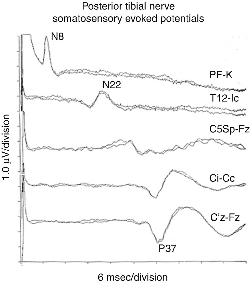
Lower Extremity SEPs
Related posts:


Stay updated, free articles. Join our Telegram channel

Full access? Get Clinical Tree


