Fig. 1
Pre-surgical MRI to determine surgical coordinates. (a) Animals are anesthetized and fitted into an MRI-compatible stereotaxic head frame by first securing the animal into the ear bars, followed by the palate and eye bars. (b) The scan is obtained using a surface coil that sits directly above the animal’s head
5.
Disconnect the animal’s breathing tube from the anesthesia machine and quickly transfer the animal placed in the head frame to the MRI table (still prone and head first) and reconnect to the anesthesia machine located in the MRI unit (see Note 2 ).
6.
Place a circulating warm water pad and towels under the animal on the MRI table and place extra towels over the animal order to maintain body temperature.
7.
Attach peripheral physiological (pulse rate/oxygen saturation, ETCO2, respiration, and/or noninvasive blood pressure) monitors to the animal (digit cuffs) and observe for accuracy and reliability of readings. From the control room, an MRI technician should continue to monitor the animal’s respiratory rate, pulse rate, end tidal CO2 and oxygen saturation (see Note 3 ).
8.
Tape a fiducial marker to right side of the animal’s head to use as a reference on the MR image (see Note 4 ).
9.
Place the surface/head coil (Fig. 1b) directly above and parallel to the animal’s head such that it is centered over the scanning area of interest (caudate and/or putamen, approximately 12–25 mm in front of the ear bars) for HD gene therapy studies. The coil should be approximately 0.5–1.0 cm above the surface of the head but not touching the skin (see Note 5 ). Center the animal’s head on MRI table using the laser crosshair feature on the MRI scanner and then send the animal into the center of the magnet.
10.
First collect a quick, single-slice, three-axis localizer scan that gives a view of the animal’s head in the three scanner-frame axes (voxel size 1.0 × 1.0 × 1.0). This ensures that the coil is functioning properly and allows for further refinement around the scanning area of interest (1–2 min scan).
11.
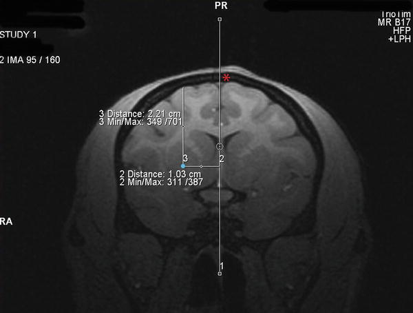
Next collect a T1-weighted structural scan (MPRAGE) scan to establish the surgical coordinates (voxel size: 0.5 × 0.5 × 0.5, 12 min scan; see Note 6 ). Coordinates are determined from coronal scans using the MRI software Distance Tool as follows: (1) Anterior/Posterior (AP) determined by establishing the MR image containing your injection region of interest (i.e., caudate or putamen) and calculating the distance (in millimeters (mm)) in front of or behind the MR image containing the ear bars (ear bar contrast dye is evident on scan), (2) Medial/Lateral (ML) established by determining the distance (mm) from the center of the two hemispheres to the proposed injection site (draw a vertical line through the center of the sagittal sinus vein as a reference), and (3) Dorsal/Ventral (DV) established by determining the distance from the pial surface to the proposed injection site (Fig. 2, red asterisks indicates the sagittal sinus vein and the blue dot indicates the injection site in the rhesus putamen; see Note 7 ). Record surgical coordinates on a piece of paper that will go with you into the operating room.


Fig. 2
Determining surgical coordinates from the MRI scan. Surgical coordinates an for injection site into the putamen (shown by a blue dot) are created by using the MRI software to establish (1) the distance in mm in front of the ear bars (AP coordinate), (2) the distance in mm lateral to the center of the sagittal sinus vein (ML coordinate, shown by a red asterisks) and (3) the distance in mm ventral to the pial surface of the brain (DV coordinate)
12.
When the scan is finished, the animal can be removed from the magnet, disconnected from physiological monitors and anesthesia tubing, placed back onto the mobile anesthesia cart, reconnected to anesthesia on cart, and wheeled into the operating room.
3.2 Stereotaxic Injection into the Caudate and Putamen
1.
Disconnect animal from anesthesia and remove from mobile anesthesia cart. Place animal onto the surgical table and connect endotracheal tube to surgical anesthesia unit. Maintain animal on 1–2 % Isoflurane combined with 100 % oxygen administered at a rate of 1–1.5 l/min (see Note 8 ). Secure the base of stereotaxic frame to the table with surgical tape (animal’s torso and legs must be delicately lifted up to achieve this, while head remains locked into frame) and place physiologic monitoring equipment on the animal.
2.
Administer preoperative doses of Hydromorphone HCl (2 mg/ml) (range of doses: <3 kg bodyweight, 0.5 mg, 0.25 ml; 3–10 kg bodyweight, 1 mg, 0.5 ml; >10 kg bodyweight, 2 mg, 1 ml) intravenously and 25 mg/kg Cefazolin intravenously as well as every 2 h intraoperatively (for both drugs).
3.
Establish intravenous fluids (Lactated Ringers solution) @ 10–20 ml/kg/h. Fluids may be increased based on hydration status of patient or due to blood loss during surgery.
4.
Apply a ChlorPrep (a chlorhexidine/alcohol instant solution) to the entire surgical site and allow it to dry. Drape surgical areas with sterile towels.
5.
Place a warm forced air system (Bair hugger) around the animal, as well as warm water bags, for the duration of the surgical procedure. Place a full table drape over the animal, towels and Bair hugger to avoid any potential breaks in aseptic technique due to the necessary manipulation of the stereotaxic manipulator.
6.
Surgical staff should wear hair bonnets, surgical masks, protective eyewear and gloves prior to entering the operating room. Surgeons should perform a full pre-surgical sterile scrub with a chlorhexidine or betadine solution. Surgeons should wear sterile gowns and sterile surgical gloves prior to draping the patient and initiating the surgical procedure.
7.
Open sterile (ethylene oxide sterilized) surgical packs containing instruments, drill, micromanipulator, AP zeroing bar, surgical pump, needles/syringes and supplies on a flat surface near the operating table.
8.
Assemble needles and syringes and wet the syringe barrels by withdrawing and expelling injection vehicle (saline, PBS, buffer, etc.) several times (see Note 9 ).
9.
Slide the micromanipulator onto the AP zeroing bar and tighten down anywhere.
10.
Screw the AP slide attachment onto the micromanipulator and tighten down (use Allen wrench if necessary).
11.
Screw the infusion pump onto the AP slide attachment and set/lock AP slide attachment to a set number (example 50 or 0; all AP coordinate measurements from the MRI will be added or subtracted from this number, depending on whether the micromanipulator is placed on the left or right AP bar on the animal’s head frame).
12.
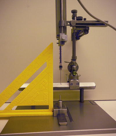
Place the syringe/needle into the infusion pump and lock into place. Use a T-square (e.g., PolySquare) to make certain that the micromanipulator, pump, syringe and needle are straight and make adjustments if not (Fig. 3).


Fig. 3
Zeroing the AP slide bar. Prior to securing the micromanipulator on the animal’s head frame in the surgery room, the AP slide bar must be zeroed out by setting the AP slide bar to a predetermined number (example, 50) and lining up the tip of the needle/cannula with the point structure on the AP zeroing plate. When the micromanipulator is placed into the exact position on the AP bar of the head frame, the needle tip will be located at the ear bars. Using a T-square when zeroing the AP slide bar helps to ensure that the needle is straight
13.
Ensure that all components of the micromanipulator are tightened appropriately (use Allen wrenches).
14.
Carefully loosen the micromanipulator from the AP zeroing bar and slide laterally to line up the tip of the needle with the point structure on the AP zeroing plate. Record the number on the AP zeroing bar (not the AP slide attachment). When the micromanipulator is placed at the same number on the animal’s head frame AP bar, the needle will be correctly positioned at the ear bars (ear bar zero).
15.
Administer 25 mg/kg of Cefazolin intravenously prior to making the initial scalp incision for antibiotic coverage. Inject an intradermal, local block at the proposed incision site consisting of 0.4 ml (up to 0.8 ml depending on size of incision) Bupivacaine (0.5 %) combined with 0.1 ml (up to 0.2 ml depending on size of incision) and Lidocaine (1 %) with epinephrine.
16.
Make a linear sagittal incision of approximately 6 cm length across the top of the animal’s scalp. Elevate the subcutis and periosteum and retract laterally to expose the skull. Sharply dissect muscle attachments and retract laterally.
17.
Drill a 1 cm long line close to the planned injection site (caudate and/or putamen) perpendicular to the sagittal sinus. Extend the drill line down to the level of the dura to expose the dark sagittal sinus vein. The exposed sagittal sinus vein will be used to establish the ML zero point.
18.
Bring the micromanipulator (connected to the pump, syringe and needle) from the AP zero bar to the animal’s head frame and lock into place on either the left or right AP bar at the number recorded earlier (see Note 10 ). Use the AP slide attachment and the ML dials on the micromanipulator to bring the needle to the center of the sagittal sinus vein and record the ML number as the zero point.
19.
Calculate the AP and ML coordinates for each injection site (see Note 11 ) and use the micromanipulator to bring the needle to those sites and mark the sites on the skull with a pencil or permanent marker (Sharpie).
20.
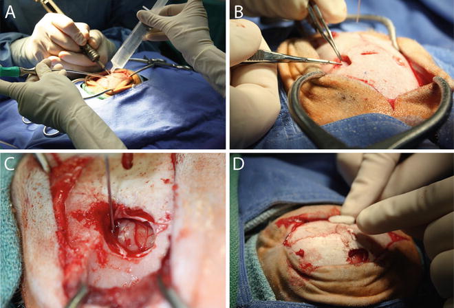
Create oval craniotomies over the proposed injection sites using a high speed surgical drill with a 2 mm carbide burr (Fig. 4a). The length and diameter of the craniotomies will vary depending on the number of proposed injection sites in each hemisphere. Use saline and suction to cool the drill bit and clear bone debris from the craniotomy area. Smooth the edges of the craniotomies with rongeurs and incise the dura with a 22 gauge needle followed by microdissection scissors (Fig. 4b).


Fig. 4
Stereotaxic injection into the caudate and putamen. (a) A craniotomy that encompasses the proposed injection site(s) is established using a high speed drill and a 2 mm carbide burr. The edges are rounded using a rongeur. (b) The dura is excised using a micro-scissor and folded back to expose the pial surface of the brain . (c) The needle is slowly lowered to the calculated injection site coordinate and the infusate delivered using an infusion pump set to either a constant or ramping injection rate. (d) Post-injection, the needle is slowly raised and the craniotomy is filled with Gelfoam prior to suturing
21.
Load the syringe with infusate without removing the syringe from the infusion pump (see Note 12 ) and prime the needle by using the infusion pump to infuse until a small amount of liquid is visible at the tip of the needle. Swab the infusate away with gauze or a surgical swab.
22.


At each injection site, carefully lower the needle down to the pial surface and record the DV value on the micromanipulator, which will serve as the DV zero value. Calculate the DV coordinate by subtracting the DV value obtained from the MRI from the DV zero value.
Stay updated, free articles. Join our Telegram channel

Full access? Get Clinical Tree


