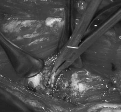
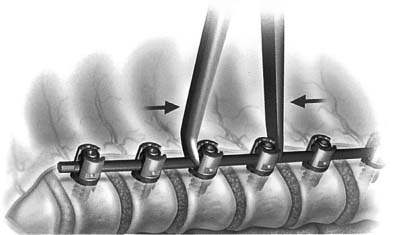
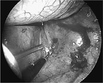
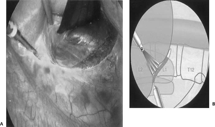
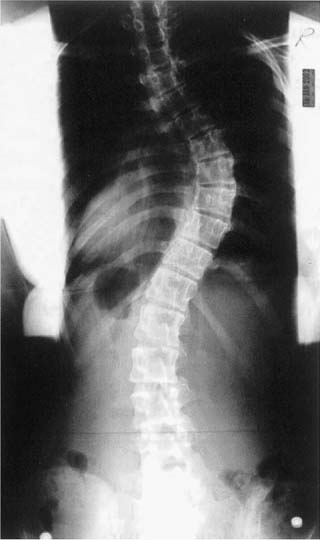
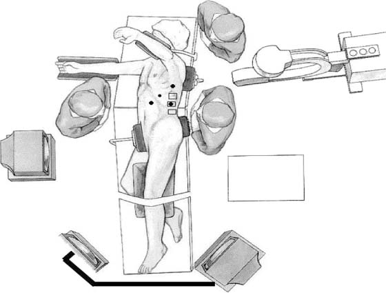
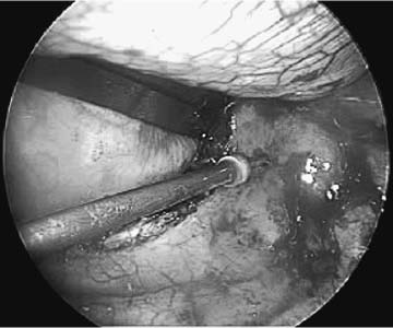
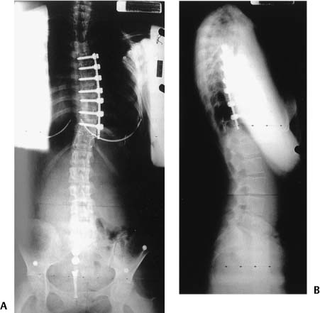
Chapter 20 The technological advances made within spinal surgery have increased dramatically within the past two decades. This advancement has progressed to the field of spinal deformities, leading to less invasive and more accurate placement of instrumentation. This advancement has been seen in patient satisfaction, with minimally invasive procedures causing less physical harm to tissue. Technological advances include optics in three dimensions and high definition (HD), instrumentation, image guidance, intraoperative imaging, intraoperative monitoring, and use of robotics. This chapter is divided into three main sections: minimally invasive surgery, image guidance, and robotics. Innovative techniques, from the use of the operating microscope to image guidance, have changed our approach to problems in the operating room. In addition, improved instrumentation (from odontoid screws and lateral mass screws to sacropelvic fixation) has improved the surgical management of countless patients. It is these changes that have collectively led to the advancement of spinal surgery and subsequent improved outcomes. One of the major advances within the past decade has been in the development of minimally invasive spinal surgery. Since its inception, progress has been very rapid. From percutaneous procedures to multilevel fusions, the advances in this field have been unparalleled. Furthermore, similar technology and techniques have been used in the treatment of spinal deformity. Advances in this arena include thoracoscopic and laporacopic decompressions, releases, placement of instrumentation, and deformity correction. The indications for anterior surgery for the correction of spinal deformity are discussed in another chapter. This section will focus on the minimally invasive approaches for scoliosis reduction. Although the goals of minimally invasive surgery (MIS) are the same as the goals for open reduction, added benefits include less tissue trauma, decreased blood loss, decreased pain and time for rehabilitation, and smaller incisions. This approach, however, requires special attention to details and has a large training curve—as with other MIS procedures.1 Therefore, the minimally invasive spine surgeon should be well versed in open techniques and other endoscopic spine procedures.2 Anterior thoracic scoliosis correction is kyphogeneic by nature.3 Thus, it finds a niche with adolescent idiopathic scoliosis (AIS), which is generally hypokyphotic with an anterior column overgrowth. In addition to curves greater than 40 degrees but less than 80 degrees, the curve pattern should be amenable to instrumentation from T4 to L1. For patients demonstrating angles greater than 70 degrees, combined approaches may allow for more adequate reduction. Because anterior scoliosis correction is kyphogenic contraindications include patients with kyphosis at that level. Angles greater than 30 degrees should be avoided because of the potential for instrumentation failure and neurologic injury. In addition, the pleural cavity should be amenable to thoracoscopic surgery. As with any thoracoscopic procedure, contraindications include pneumonia, pleural effusion, pleural adhesions, and inability to tolerate single-lung ventilation. Figure 20–1 A graphical depiction of a patient positioned within the operating room. As is true for all of spine surgery, positioning and patient preparation is essential. In addition to thoracoscopic instruments, surgical equipment should include high-quality endoscopes and cameras, two monitors, and a radiolucent table. Intraoperative somatosensory evoked potentials (SSEPs) and motor evoked potentials (MEPs) are obtained. Anesthesia is induced with the capabilities of single-lung ventilation. The patient is placed in a lateral decubitus position on a radiolu-cent table with the convex side of the scoliotic curve facing upward. After the pressure points, axilla, head, and neck are addressed, the patient can be secured to the table (Fig. 20–1). The surgeon should stand opposite to the assistant, and both should feel comfortable with the table height and position of the monitors. Fluoroscopy may be used to visualize the level, and skin marks are made at selected levels and for future portal sites. Generally, one or two portals along the anterior axillary line will facilitate scope placement. On occasion, a fan retractor is placed for lung retraction. Circumferential spine exposure is then accomplished with cautery. K-wires may facilitate fluoroscopic verification of the level involved. The segmental vessels are carefully dissected and may be sacrificed with clips (Fig. 20–2). Then, disk excision is accomplished. Placement of instrumentation is facilitated with the surgeon’s familiarity of anatomy and fluoroscopic verification. As an optimal entry point is along the midvertebral body just anterior to the rib head, an awl is used to define an entry point. Tapping facilitates screw placement, and screw length can be determined by probing the depths of a tapped hole. Optimal screw length engages into the contralateral cortex, with the understanding that proper trajectory is essential. Cannulated screws may be used with a trajectory set by a K-wire placed within the vertebral body. In this situation, calibrated K-wires facilitate screw length choice (Fig. 20–3). Figure 20–2 Thoracoscopic scoliotic deformity reduction. Dissection and clipping of segmental vessels. Figure 20–3 Endoscopic placement of thoracic anterior screws with a cannulated screw system. Placement of K-wire. Rod length is determined with a ball-cable ruler or calibrated malleable template. Placed along the convex side, the shortening of the spine must be taken in consideration in the rod measurements. The rod is secured to the caudal screw via a screw cap. After an interbody spacer (allograft or autograft) is placed within the disk space above, the subsequent rostral screw is secured with compression. Fixating the rod to more rostral screws may be difficult because of the convexity of the spine. On these occasions, an approximator-cap inserter tool is used. Aggressive manipulation of the rod-screw construct may lead to weakening of the screw-bone interface (Fig. 20–4). After deformity correction, hemostasis, and irrigation, a chest tube is placed and closure is started. While the lung is reinflating, pleural closure can be accomplished directly or with an endoscopic stitching device. Then, standard closure of all of the incisions is finished. Figure 20–4 Graphical representation of rod fixation with segmental compression. Figure 20–5 Thoracoscopic view of the diaphragm: defining the outer margin of the diaphragm. Through a thoracoscopic approach and retraction of the diaphragm, exposure to L2 is possible. On occasion, the diaphragm is split to facilitate more caudal exposure4 (Figs. 20–5 and 20–6). When more caudal exposure is necessary for deformity correction, a retroperitoneal or laparoscopic approach to the anterior lumbar spine may be accomplished. MIS of the anterior lumbar spine has also advanced with thoracoscopic surgery. Attention has turned to minimally invasive retractors. Unfortunately, there is no system that has prevailed. The systems that have been marketed are balloon technology,5 Laprolift (Origin Medsystems, Menlo Park, California)6 and CO2 inflation. Although thoracoscopic anterior fixation was demonstrated to be effective in idiopathic scoliosis that was hypokyphotic, combined approaches may allow for posterior fixation to correct kyphotic deformities within the sagittal plane. In addition to the thoracoscopic methods mentioned above in a lateral decubitus position, thoracic anterior release has been accomplished in a prone position.7 This facilitates the use of posterior instrumentation while releasing anteriorly in the same setting. The same indications and contraindications for MIS in the lateral decubitus position are true for the prone position. In addition, a small anteroposterior diameter of the chest wall and small scoliotic curvature may hamper proper placement of the thoracic trocars and working channels. Although curves greater than 40 degrees may require anterior release, curves less than 75 degrees may have rib interspaces that are too small to tolerate a 10-mm-diameter endoscopic portal. When the patient is positioned prone, the patient is prepared to the anterior axillary line. When the patient is in a lateral decubitus position, the convex side is placed upward; when the patient is in a prone position, the surgeon may enter the convex or concave side for kyphosis correction. Although the convex side may allow easier access to the disk spaces and provide a larger rib interspace for entering, the convexity leads to difficulty in releasing the extreme rostral and caudal interspaces. After the first portal is placed, the remaining portals may be placed in a V or L shape. A prone position facilitates lung retraction, as the lung and mediastinal organs relax. After proper localization, diskectomies are performed. Diskectomies may be facilitated with distraction using the posterior instrumentation. Once the anterior release is accomplished, interbody spaces are placed. Spacers include allograft or autograft. Finally, a chest tube is placed and closure is accomplished in a similar fashion to that mentioned above. With increasing thoracoscopic/laparoscopic experience, improvements have been made in surgical techniques, implants, and instrumentation. While these improvements continue, so will the advancement of MIS for anterior thoracoscopic deformity correction (Figs. 20–7 and 20–8). As stated previously, MIS can reduce morbidity relative to traditional open procedures. As surgery performed through small incisions is often less traumatic than open procedures, there is reduced postoperative pain, shortened hospital stay, and reduction in surgical complication rate. Unfortunately, these advantages do not come without cost. In addition to limitations of dexterity and tactile sensory feedback, there exists difficulty in depth perception and spatial orientation. These problems are due to a variety of factors, including monocular vision, a limited field of view, peripheral image distortions, and the projection of a natural three-dimensional (3D) surgical scene on a two-dimensional (2D) display. Figure 20–7 Preoperative anteroposterior x-ray film of a patient with a scoliotic deformity. Figure 20–8 Postoperative x-ray films of a patient with a scoliotic deformity. (A) Anteroposterior x-ray image and (B) lateral x-ray image. Image-guided surgery (IGS) systems are widely used in a variety of cranial and open spine procedures. Such systems have the promise of addressing some of the visualization problems inherent with MIS and open surgery. Fluoroscopy-based IGS overcomes some limitations and disadvantages of conventional C-arm fluoroscopy. Such systems track surgical instruments and display their position in real time on one or more previously acquired fluoroscopic images. The main components of a fluoroscopy-based IGS are a computer workstation with a monitor, a conventional C-arm fluoroscope with a calibration device that attaches to the imaging head of the fluoroscope, a tracking system including a spine clamp with a dynamic reference frame, and a variety of optically tracked instruments. An optical tracking system consists of two or more optical sensors or cameras that detect infrared light-emitting diodes (IREDs), photoreflective spheres, or photoreflective disks that are mounted on the calibration devices, the dynamic reference frame (DRF), and the surgical instruments. Using mathematical principles of localization by triangulation, the system determines the spatial position and orientation of the instruments to provide real-time navigation. Multiple instruments can be tracked simultaneously during a procedure. In the case of actively tracked instruments using IREDs, each instrument IRED array is strobed by the tracking system. In the case of passively tracked instruments, the tracking system can identify different instruments with distinct marker configurations. At the beginning of surgery, the fluoroscope is positioned in the usual fashion, the calibration device is attached to the imaging head, and the fluoroscope is draped within the field (Fig. 20–9). The DRF is attached to the spinous process adjacent to the area of interest (Fig. 20–10).
Technological Advances in Spinal Deformity Surgery
♦ Minimally Invasive Surgery
Thoracoscopic Approach and Placement of Minimally Invasive Instrumentation for Deformity Correction
Indications and Surgical Considerations
Surgical Procedure
Thoracoscopic Approach and Minimally Invasive Instrumentation for @deleformity Correction of the Thoracolumbar Spine
Surgical Procedure
Combined Prone Position Anterior Release and Posterior Instrumentation
Indications and Surgical Considerations
Conclusion
♦ Computer Assistance and Image Guidance
Fluoroscopy-Based Image-Guided Surgery
![]()
Stay updated, free articles. Join our Telegram channel


Full access? Get Clinical Tree


