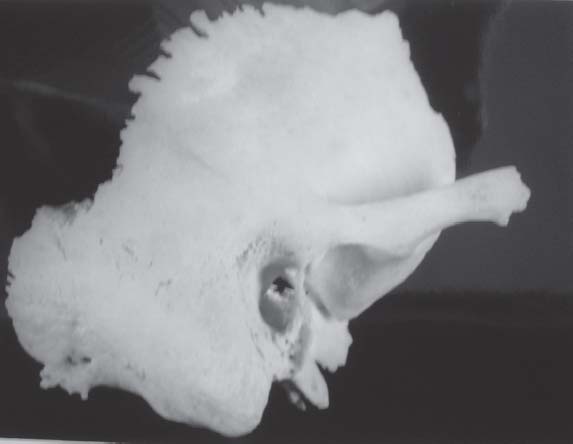
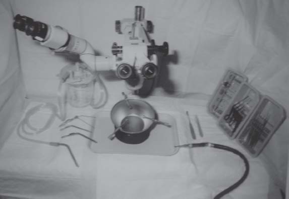
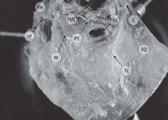
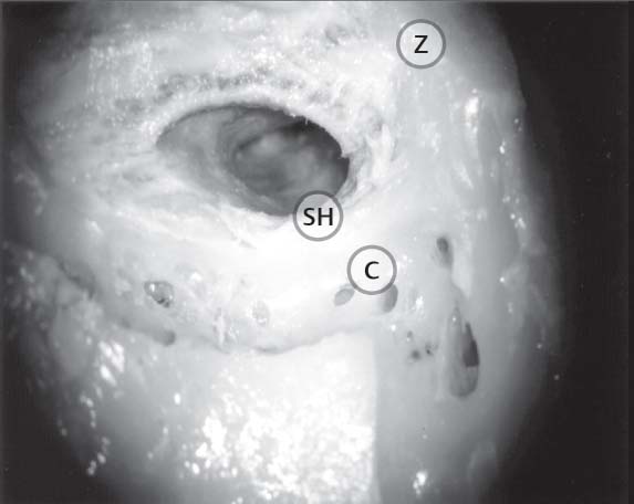
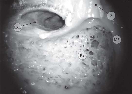
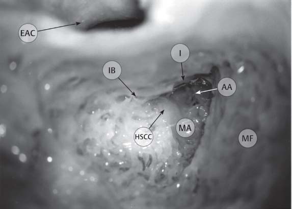
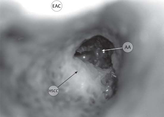
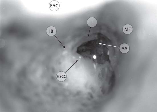
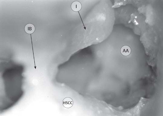
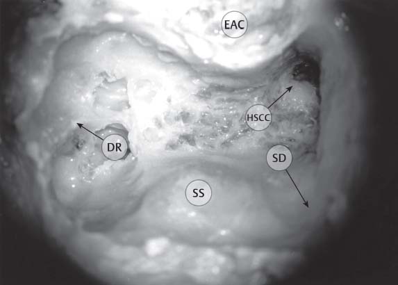
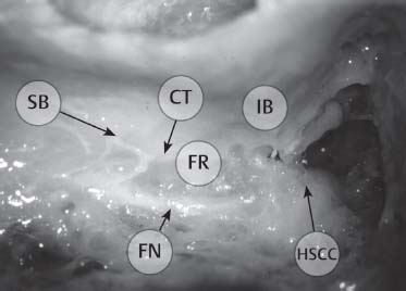
7 Temporal Bone Dissection Retrolabyrinthine/Infralabyrinthine Supralabyrinthine/Supracochlear Internal Auditory Canal (Translabyrinthine) Endolymphatic System and Inner Ear Otologic and neurotologic skull base surgery requires a thorough knowledge of temporal bone anatomy. This familiarity goes well beyond that which can be obtained by reading the pertinent textbooks. A great number of neurologic, vascular, sensory, and supporting structures crowd the ~16 cm3 space within the temporal bone. Ear surgeons must have an understanding of the three-dimensional relationships of what is arguably one of the most complex bony areas of the body. Repetitive laboratory dissection of human temporal bone specimens creates an eye–hand familiarity that is essential for safe operating in the live patient. These skills, obtained in the temporal bone dissection laboratory, are unique and cannot be mastered through substitute educational materials. Moreover, continued reinforcement of these skills is necessary throughout the duration of active surgical practice. The temporal bone specimen should be trimmed to fit comfortably in the dissection bowl. For example, an excessive amount of squamosa may interfere with secure placement and orientation of the specimen. The anatomical dissection exercises in this manual approach the temporal bone from three sides: mastoid (lateral), middle fossa (superior), and posterior fossa (posterior). Soft tissues should be removed to allow the exposure seen in the illustrations for each approach. In general, the bone should be mounted in the surgical position to begin the exercise. It may be reoriented as the dissection proceeds for better visualization of deeper areas. It should be remembered that the dissections in this manual are designed to emphasize the identification of anatomical structures and their respective relationships, rather than to illustrate the exact steps of a specific surgical procedures. Fig. 7.1 Entire temporal bone—soft tissues removed. The set-up for temporal bone dissection requires magnification, illumination, a surgical drill, suction and irrigation equipment, and a few otologic instruments. Typically, the temporal bone dissection station should include a dish with screws to immobilize the bone. Visualization is an integral part of temporal bone dissection. A surgical microscope that is illuminated by either a halogen or xenon light source provides magnification and visualization. High-vacuum suction and water irrigation should also be available on a continuous basis to remove the bone fragments from the dissection field. Frequently used instruments are listed below: • High-speed otologic drill (pneumatic or electric) • Irrigating suctions • Otologic suctions (no. 3, 5, 7, 10) • Hosing for both suction and irrigation • No. 15 blade scalpel • Heavy periosteal elevator • Round knife • Annulus elevator • Curved needle • Microscissors Visualization is an integral part of dissection. Fig. 7.2 Typical surgical set-up. The positioning of the surgeon and the bone are critical aspects for temporal bone dissection. The surgeon should be comfortable, seated in a straight-back chair with both feet on the ground under the table on which the dissection is being performed. The temporal bone is positioned in a secure bone holder in the surgical position. This requires the bone to be placed with either the anterior (lateral and posterior approaches) or inferior aspect (superior approach) of the bone facing away from the surgeon. The surgeon’s hands and arms should be able to rest on the table for stability while dissecting. The microscope is suspended from an articulating arm that should enter the field from an anterior or lateral direction. The footpedal for the drill is under the table. The surgeon should sit comfortably. The surgeon’s hands and arms should rest on the table or on designated armrests on the chair. Use of the suction–irrigating equipment requires some practice. The flow of water should be rapid enough to remove the bone dust but not so fast as to obscure visualization. This can usually be accomplished by regulating the flow of water so that the water flows freely when the thumb is off the aspiration hole and is completely aspirated when the thumb is over the hole. During dissection, the suction–irrigator should be positioned so as to allow the water to flow into the area in question but not to obscure visualization. Flow of water should remove bone dust and should ensure good visualization. Use of the high-speed surgical drill also requires practice. Anatomical dissection of the temporal bone structures requires careful identification and preservation. To accomplish this, the surgeon should drill parallel to major structures to avoid transection or inadvertent removal. The largest burrs should be used whenever possible to provide a stable mode of dissection and avoid deep cutting into small unexposed areas. The cutting burrs are fluted, thus providing for aggressive bone removal when needed. When using these burrs, three-sided contact with the bone should be avoided as this may make the drill bite deeply into the bone. The diamond burrs are smoother and thus better for fine, detailed work. Use of the diamond burrs requires prolonged contact with the bone. In the past, drills operated at substantially lower speeds (<15 000 rpm). Using those drills, a change in sound and tactile response of the burr touching bone was useful for identifying the proximity to critical structures (i.e., dura and large blood vessels). However, with the new high-speed drills (>20 000 rpm), chatter and digging are markedly reduced, although this comes at the expense of sound and tactile feedback. Drill parallel to major structures. The largest burr possible should be used. As in all anatomical dissections, the exercise should follow a step-wise progression from superficial to deep structures. Thus, the topography and soft-tissue details of the temporal bone should be appreciated before the dissection is begun. Upon removing superficial structures, recognize that these are the landmarks to the deeper structures. As the deeper structures are appreciated, these form the landmarks for the next level of dissection. Frequent appreciation and reflection is necessary to understand this concept. Superficial structures serve as landmarks for deeper structures. The temporal bone comprises five distinct sections attached at bony sutures, termed the squamous portion, the mastoid portion, the tympanic portion, the petrous portion, and the zygomatic process. Numerous irregularities create the important landmarks on the lateral surface of the temporal bone. As the drilling exercises outlined in the subsequent section illustrate, taking the time to study these landmarks and their relationships to structures on the medial surface of the temporal bone leads to greater facility with bony dissection. Five sections of the human temporal bone • Squamous • Mastoid • Tympanic • Petrous • Zygomatic Dissection of the temporal bone from the lateral aspect is the most common approach for the vast majority of otologic procedures. The components of the lateral dissection include: • Topography • Cortical mastoidectomy • Facial recess • Extended facial recess • Retrolabyrinthine/infralabyrinthine • Supralabyrinthine/supracochlear • Labyrinthectomy • Internal auditory canal (translayrinthine) • Canal wall down mastoidectomy • Canal wall down with labyrinthectomy • Canal wall down with internal auditory canal • Infracochlear • Transcochlear The surface landmarks that form the basis for the initial descent into the mastoid include the mastoid tip, the digastric muscle, the spine of Henle, the cribriform area, the temporal line, the external auditory canal (EAC), and the root of the zygoma. To identify these structures, the soft tissues over the bone must be reflected or removed. Roughly, the temporal line lies somewhat below the level of the middle fossa plate (dura) in most bones, and the spine of Henle and the cribriform area approximate the level of the mastoid antrum. The mastoid tip is inferior to the stylomastoid foramen and the digastric muscle approximates the level of the stylomastoid foramen and, thus, the exit of the facial nerve (FN) from the temporal bone. Fig. 7.3 Complete temporal bone—lateral view. Structures: squamous portion (SQ), mastoid process (M), external auditory canal (EAC), root of zygoma (Z), temporal line (TL), glenoid fossa for the temporomandibular joint (TMJ), styloid process (SP), petrotympanic fissure (PT), petrous apex (PA). The temporal line lies somewhat below the level of the middle fossa dura. The initial entry into the temporal bone is directed at locating the mastoid antrum. Drilling should begin in the angular region bounded by the temporal line superiorly and the root of the zygoma and the EAC anteriorly. The dissection should continue superiorly and anteriorly until the middle fossa plate is identified and the EAC is thin anteriorly. The middle fossa plate always courses medially to form the roof of the mastoid antrum, thus providing a safe means for identifying this important air cell within the temporal bone. During the initial descent, a wide field of view should be maintained and Koerner’s septum (continuation of tympanomastoid suture) should be identified and removed. Within the antrum, the horizontal semicircular canal (HSCC) and incus buttress should be identified. Finally, progressive anterior drilling in the antrum will uncover the short process of the incus. The posterior and inferior aspects of the mastoid can then be excavated, the sigmoid sinus identified posteriorly, and the sinodural angle deepened. The inferior limit of dissection should include the digastric ridge, a fibromuscular impression of the digastric muscle and groove. The middle fossa plate provides a safe means for identifying the mastoid antrum. Fig. 7.4 Cortical mastoidectomy: Identify surface structures. Structures: spine of Henle (SH), cribriform Cortical Mastoidectomy Fig. 7.5 Cortical mastoidectomy: Thin the external auditory canal and middle fossa plate (mastoid tegmen). Structures: external auditory canal (EAC), middle fossa plate (MF), pneumatized root of zygoma (Z), Koerner’s septum (KS). Fig. 7.6 Cortical mastoidectomy: Open the lateral wall of the mastoid antrum (i.e., Koerner’s septum) and proceed anteriorly until the short process of the incus is visible. Structures: posterior wall of external auditory canal (EAC), mastoid antrum (MA), aditus ad antrum (AA), horizontal semicircular canal (HSCC), short process of incus (I), incus buttress (IB), middle fossa plate (MF). Fig. 7.7 Cortical mastoidectomy: The use of water reflection may help visualization. This image depicts the view of the antrum without the use of water (compare with Fig. 7.8 with water). Structures: posterior wall of external auditory canal (EAC), aditus ad antrum (AA), horizontal semicircular canal (HSCC). Fig. 7.8 Cortical mastoidectomy: The use of water reflection as shown here may help visualization of the incus (compare with Fig. 7.7 without the use of water). Avoid drilling on the incus (Fig. 7.9). Structures: posterior wall of external auditory canal (EAC), aditus ad antrum (AA), horizontal semicircular canal (HSCC), short process of incus (I), incus buttress (IB), middle fossa plate (MF). Fig. 7.9 Cortical mastoidectomy: Avoid drilling on the incus; see flattened short process. Structures: aditus ad antrum (AA), horizontal semicircular canal (HSCC), short process of incus (I), incus buttress (IB). Fig. 7.10 Cortical mastoidectomy: Remove posterior (perisigmoid sinus) and inferior (mastoid tip) cells. Structures: posterior wall of external auditory canal (EAC), horizontal semicircular canal (HSCC), sigmoid sinus (SS), sinodural angle (SD), digastric ridge (DR). The white nerve sheath should be identified through the yellow bone. The facial recess (i.e., posterior tympanotomy) is a triangular region bounded by the facial nerve medially, the chorda tympani nerve laterally, and the fossa incudis superiorly. The region of the facial nerve where the chorda tympani nerve fibers exit is referred to as the chorda–facial angle and can be found in a variable location along the mastoid segment. The chorda tympani nerve then courses anteriorly and superiorly in the EAC to enter the middle ear space on the lateral aspect of the facial recess. The facial recess is frequently pneumatized and progressive drilling near the fossa incudis superiorly, within the confines of the chorda tympani and facial nerve, will open the middle ear. In most instances, a small sensory branch of the facial nerve can be identified superior to the chorda tympani nerve takeoff, coursing inferolaterally in the EAC. This nerve lies posterior to the chorda tympani nerve. Through the posterior tympanotomy the following structures should be visualized: stapedius tendon exiting the pyramidal process; long process of the incus; incudostapedial joint; stapes superstructure; round window niche and promontory. The tympanic (i.e., horizontal) segment of the facial nerve should also be identified coursing in an anterior direction superior to the stapes and the cochleariform process. The cochleariform process anchors the tensor tympani tendon medially, as it tracks toward the neck of the malleus. A tangential view through the facial recess and medial to the neck of the malleus can frequently reveal the eustachian tube (ET) opening into the middle ear. Facial recess: triangular region bounded by the FN, the chorda tympani nerve, and the fossa incudis. To expose the inferior portion of the middle ear and hypotympanum, the facial recess can be extended inferiorly by transecting the chorda tympani nerve and EAC sensory nerve while progressively drilling on the anterior and lateral sides of the descending segment of the facial nerve. In this maneuver, the tympanic annulus is identified and followed around the inferior part of the tympanic ring. All of the bone inferior to the EAC can be removed.The jugular bulb may be encountered during the medial, anterior portion of this dissection as the floor of the posterior middle ear is removed. The facial recess is frequently pneumatized .
General Considerations
Introduction
Specimen Handling (Fig. 7.1)
Laboratory Set-up (Fig. 7.2)
Position
Dissecting Technique
The Temporal Bone
Lateral Dissection
Topography (Fig. 7.3)
Cortical Mastoidectomy (Figs. 7.4, 7.5, 7.6, 7.7, 7.8, 7.9, and 7.10)
Facial Recess (Figs. 7.11, 7.12, and 7.13)
Extended Facial Recess (Figs. 7.14, 7.15, and 7.16)
Related posts:
![]()
Stay updated, free articles. Join our Telegram channel

Full access? Get Clinical Tree


Temporal Bone Dissection
Only gold members can continue reading. Log In or Register to continue

