Chapter 36 Transaxial Anterior Lumbar Interbody Fusion Using The AxiaLIF System
The rate of minimally invasive spine surgery (MISS) has increased in recent years because of the development of technology and new approaches to the spine. Open lumbar surgery is disadvantageous because of the need of muscle and neural retraction, ligamentous and osseous dissection, disruption of the anulus, and vascular exposure [1]. For most MISS techniques, the approach is like those used in open approaches to the spine—that is, posterolateral and extraforaminal exposure of the disc space and incision or excision of the anulus [2–9].
When stabilization of the lumbosacral spine is indicated, however, a less invasive axial lumbosacral surgery offers significant advantages over MISS techniques [10–13]. This technique, transaxial anterior lumbar interbody fusion, uses a percutaneous, presacral approach. Use of the AxiaLIF System, manufactured by TranS1, Inc. (Wilmington, NC), is described in this chapter, first for stabilization at one level, and then for stabilization at two levels.*
Presacral anatomy
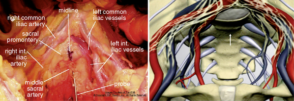
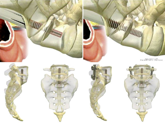
Axial anterior spinal access is accomplished by dilating an osseous tract through the upper sacrum. The midline entry point in to the sacral promontory at approximately the S1-S2 interspace is relatively bare area compared with the more complex vascular and neural structures encountered over the lower lumbar spine (Fig. 36-1) [14,15]. At the sacral level, the iliac vessels and their accompanying sympathetic hypogastric nerves have diverged by several centimeters. The middle sacral artery follows a variable course over the sacrum but is usually small at the S1-S2 level. The rectum and sigmoid colon are easily mobilized in the presacral region. The presacral space is filled with areolar tissue and fat between the parietal peritoneum on the anterior sacrum and the visceral peritoneum on the rectum (see Fig. 36-1). The space is relatively easily traversed with a blunt obturator or needle.
AxiaLIF at one level
Procedure
Patient Positioning
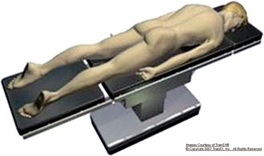
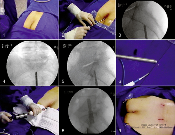
In the AxiaLIF technique, multiplanar imaging with magnetic resonance (MRI) and/or computed tomography (CT) is essential to determine whether the patient is a proper surgical candidate. A standard bowel preparation is performed. The patient is placed on a fluoroscopically compatible surgical table in the prone position (Fig. 36-2). Bolsters are positioned under the hips and shoulders to raise the sacrum and establish proper lumbosacral posture. A catheter is inserted into the rectum to allow insufflation of air. The operative site is prepared with an adhesive barrier to exclude the perineum. Two C-arm fluoroscopic units are positioned to allow frontal and lateral (biplanar) fluoroscopic visualization of the lumbosacral region. The procedure is currently performed using general anesthesia.
Approach
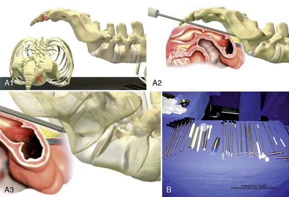
The AxiaLIF technique provides percutaneous access to the lumbar spine through the anterior presacral space (Fig. 36-3A). The developed instruments facilitate a safe and reproducible entrance to the L5-S1 disc space (Fig. 36-3B).
Radial Discectomy
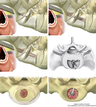
Axial disc access is accomplished through the 9-mm sacral working cannula. Custom MISS instruments for discectomy, end plate preparation, tissue removal, and bone grafting are inserted through the working cannula (Fig. 36-4). The instruments are monitored with biplanar fluoroscopy. Axial disc space entry facilitates the use of expansible, radial instruments that are aligned in the plane of the disc space and end plates. Thus minimally invasive discectomy is potentially easier and more complete with axial disc space entry than with horizontally oriented, posterolateral approaches.
Distraction and Dynamic Decompression
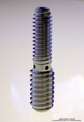
For the distraction, a 14-mm rod is inserted and engages the entirety of the transosseous tunnel from the sacrum to the L5 vertebral body. The rod is a proprietary temporary titanium device with a lumbar diameter of 9 mm and a sacral diameter of 12 mm. The differing diameters allow the rod to have two different thread pitches. When the rod is implanted (Fig. 36-5), its differential pitch produces distraction of the vertebral bodies at a rate that depends on the difference of the thread pitches. This dynamic distraction allows the surgeon to accurately reproduce the required disc height restoration and indirectly decompress the neural foramen.
Treatment Alternatives
Case Series [16,17]
Assessment consisted of the following:
 Measurement of disc height and fusion through radiography and CT evaluation by an independent radiologist
 Pain assessment by means of a visual analog scale (VAS), Oswestry Disability Questionnaire, and the SF-36 Health Survey
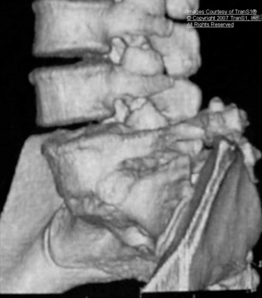
A 45-year-old woman had discogenic-type low back pain that intensified with standing and flexion. In addition, she had neurogenic claudication symptoms. Preoperative MRI and radiography showed narrowing and desiccation of the L5-S1 disc space with a spondylolisthesis grade II (Fig. 36-7). She underwent the AxiaLIF procedure at the L5-S1 level (Fig. 36-8). Radiographs obtained 12 months after surgery showed osseous bridging of L5-S1 and reduction of the spondylolisthesis (Fig. 36-9). CT scans demonstrated no evidence of radiolucency on the pedicle screws and the distraction rod (Fig. 36-10) and, along with a three-dimensional reconstruction, also showed solid osseous fusion of the L5-S1 interspace (Fig. 36-11).
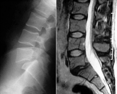
Figure 36–7 Case Study 36.1: Preoperative sagittal MRI (B) and lateral radiograph (A) shows narrowing and desiccation of the L5-S1 disc space with a spondylolisthesis grade II.
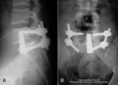
Figure 36–9 Case Study 36.1: Lateral (A) and anteroposterior (B) radiographs obtained 12 months after surgery show osseous bridging of the L5-S1 interspace and reduction of the spondylolisthesis.
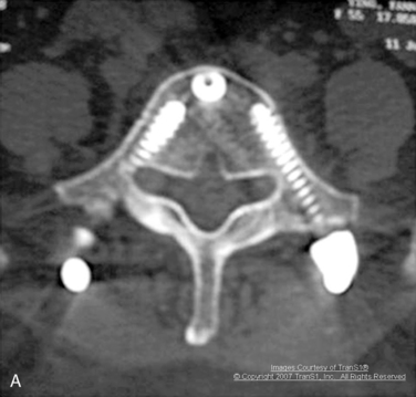
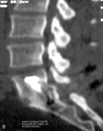
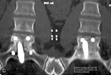
Figure 36–10 Case Study 36.1: (A) Axial computed tomography CT) scan obtained 12 months after surgery shows no evidence of radiolucency on the pedicle screws and the distraction rod. Sagittal (B) and coronal (C) CT scans demonstrates osseous fusion of the L5-S1 interspace.
in VAS, Oswestry, and SF-36 values measured again at 2 years after surgery. The mean VAS score decreased from a preoperative value of 8.3 to 3.4. The mean Oswestry Disability Index improved from 43.1 to 21.0. Radiographic analysis concluded that there was no evidence of implant back-out, damage, bone resorption, fractures, or sacral abnormalities.
Two measurements of the disc height were made preoperatively and postoperatively, one in the midline and the other in the posterior border of the disc space. Preoperatively, mean midline disc height was 6.06 (range 2-11), and mean posterior border disc height was 4.8 (range 2-9). Postoperatively, the mean midline disc height was 7.5 [range 5–11], and mean posterior border disc height was 6.06 (range 3-9). CT scans demonstrated of fusion rate to be 89.5% at 12-month follow-up, and 94.7% at 30 months after surgery (18 of 19 patients).
AxiaLIF at two levels
The AxiaLIF (Axial Lumbar Interbody Fusion) 2L System (TranS1, Inc.) includes surgical instruments for “creating a safe and reproducible presacral access route to the L4-S1 vertebral bodies [18].” The technique features instrumentation to enable standard of care fusion principles, distraction, and stabilization of the anterior lumbar column while mitigating the soft tissue trauma associated with traditional lumbar fusion through open surgical incisions. With the use of this system, the lumbar spine is accessed through an axial channel in the sacrum. This approach spares the supporting soft tissue including muscles and ligaments which reduces pain in recovery and the chances of soft tissue associated complications.
Contraindications
The AxiaLIF 2L System and procedure should not be used in patients with the following conditions:
Precautions
Preoperative
Portions of this system are supplied nonsterile and need to be cleaned and sterilized according to the instructions in the product insert [18].
Stay updated, free articles. Join our Telegram channel

Full access? Get Clinical Tree


