Chapter 144 Ventral Subaxial Cervical Fixation Techniques
Cervical Spine Anatomy
The cervical spine can be subdivided into two regions: the upper (C1 and C2) and the lower (C3-7) cervical regions. The normal cervical spine is lordotic in alignment. The upper cervical spine is unique because of its distinct anatomic arrangements, compared with the rest of the cervical spine. C1 has no centrum, and as such, is a bony ring that allows for the intrusion of the dens of C2 between the lateral masses of C1. The dens articulates with the dorsal aspect of the ventral portion of the ring of C1. The lateral masses of C1 join with the occipital condyles and C2 by kidney-shaped articulations. The C2 vertebra has many attributes of the more caudal cervical vertebra. It also has a rostral extension known as the dens or odontoid process. The pars interarticularis is substantial and projects from the lamina to attach to the lateral mass. The atlanto-occipital joint allows flexion-extension (25 degrees), as well as a minimal degree of lateral flexion (5 degrees) and minimal rotation (5 degrees). The atlantoaxial joint allows 20 degrees of flexion-extension, 5 degrees of lateral bending, and 40 degrees of axial rotation.1–3 The failure strength of the alar ligament is about 200 N, whereas that of the transverse ligament is 350 N.4 The vertebrae of the middle and lower cervical spine are relatively uniform. A unique characteristic of this region is its lordotic alignment, which may aid in spinal cord injury prevention because most axial loads are imparted symmetrically to the spine rather than with a significant flexion component. Because the addition of a flexion component to an axial load greatly increases the chance of vertebral body failure and the retropulsion of bone and disc fragments into the spinal canal, the lordotic posture thereby helps to prevent catastrophic injury.
Ventral Instrumentation
Only relatively recently have ventral instrumentation constructs been applied to the cervical region. These constructs are used to treat a variety of abnormalities of the subaxial cervical spine, including degenerative, neoplastic, and infectious processes, and trauma-related injuries. These techniques involve cervical plating systems that are applied to the ventral cervical spine to promote fusion and to maintain graft position and spinal alignment. Caspar developed a semiconstrained (semirigid or dynamic) plate system that uses a bicortical screw purchase in the vertebral body.5 Johnson et al. subsequently developed a rigid or constrained plate system that uses a screw-plate locking mechanism without bicortical purchase.6 Several commercial ventral fixation systems are available, but prior to the placement of a single implant, a surgeon should ask these questions: Is a spinal implant indicated? Is a rigid or dynamic implant optimal? Is deformity reduction, correction, or prevention required? Which system is ideal for obtaining fusion and preventing subsidence? These questions are key and require a sound understanding of biomechanical principles as they apply to the cervical spine.
Biomechanics of Ventral Subaxial Spine Constructs
Ventral Compression (Tension Band) Fixation
Unlike ventral distraction techniques, ventral compression techniques do not employ interbody struts that apply compression forces to the spine. In general, it is difficult to use rods to provide significant compression or distraction in the ventral cervical spine as can be easily achieved in the thoracic and lumbar spine. However, with the development of implants such as the DOC VCSS (DePuy Spine, Raynham, MA; discussed later in this chapter), such use has been facilitated. This device allows the application of compression using a cantilevered screw-rod system, thereby enabling preloading of the bone graft and thus increasing bone healing.
Multilevel Fixation
Multisegmental fixation is not used as extensively in the ventral as in the dorsal spine. Reasons include the often inadequate ventral longitudinal exposure and the relatively weak implant-vertebral body interface. The weak implant-vertebral body interface results from the fact that the vertebral body is primarily composed of cancellous bone. The utilization of bicortical screw purchase has been developed as a strategy to overcome this problem, but it is not without risk. Other problems encountered with multilevel constructs include subsidence—the process by which the interbody graft settles in the spine. This can be avoided when “good carpentry” techniques are employed in the preparation of the end plates and the interbody or strut graft. As previously discussed, a variety of commercial ventral plates are available on the market. These are usually classified as rigid or dynamic plates. It has been observed that dynamic plates load share more than rigid plates, thereby preventing the graft from absorbing most of the load applied to the spine.7 With multilevel constructs, the caudal end of the construct is the most likely region to fail as a result of screw loosening or hardware failure, because there is a longer moment arm and increased forces at the caudal end of the construct.8 The incidence of increased failure at the caudal end of a multilevel construct can be decreased by following a few key principles: (1) maximizing screw purchase at the caudal end of the construct, (2) using dynamic fixation, (3) using meticulous bone-grafting techniques, and (4) limiting postoperative spine motion with a rigid collar in the first few months after surgery.
First-Generation Plates
Caspar Plate System
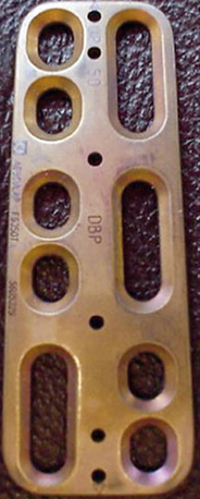
This titanium plate is nonconstrained, meaning that the screws are not locked to the plate (Fig. 144-1). The set comes with both unicortical and bicortical screws. The unicortical screws come in a variety of lengths from 10 to 28 mm. Screws have a constant outer diameter of 3.5 mm and an inner diameter of 2.2 mm. The bicortical screws are self-tapping and come in lengths from 14 to 19 mm. The outer diameter is 4 mm, and the inner diameter is 2.2 mm at the tip and 2.7 mm at the head. The screws are made of a titanium alloy with a corundum-blasted surface over a third of the length at the tip.
Techniques for Placing Caspar Ventral Cervical Plates
Prior to plate placement, distracting pins are placed in both the rostral and caudal vertebral bodies. The distracting pins are placed using a mallet and a screwdriver. The length of the plate to be used may be determined by reviewing preoperative imaging, which can be reconfirmed intraoperatively. It is important to place the plate in a manner that avoids the screw holes being placed in soft tissue or in the holes caused by the distracting pins. No screws should be placed within 2 mm of the vertebral end plates. The plate should be placed in the midline and should fit flush with the vertebral bodies. If the plate fits poorly, ventral osteophytes should be drilled off in order to ensure an adequate fit. If the curvature of the cervical spine does not allow for an adequate fit, the plate may be bent as a last resort. It is important to avoid multiple bends as this may weaken the plate. Next, the distance from the anterior to the posterior marginal line of the vertebral body is determined from the preoperative imaging, and the drill guide is set to 3 mm less than this distance. The plate is held in place with a temporary fixation pin or a plate holder. Next, the drill guide is placed into the screw holes, and the drill is used to drill the vertebral body to the preset length. Next, the screw holes are tapped and the first screw is placed. It is not fully tightened, and the rest of the screws are placed in a diagonal fashion.
Second-Generation Plates
The second-generation plates were rigid implants and have the benefits of providing rigid stabilization, maintenance of alignment, reduced need for postoperative immobilization, earlier return to function, and potentially enhanced fusion rates.9 These implants were described as restricted and constrained. Their disadvantage is that they may stress shield the bone graft and result in nonunion or implant failure. Stress shielding, as the term implies, occurs when the implant reduces fusion-promoting stresses on the bone graft, thereby leading to a nonunion.
Cervical Spine Locking Plate
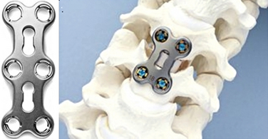
The Synthes Cervical Spine Locking Plate (Synthes CSLP, West Chester, PA) was developed and designed as a prelordosed plate. The bushings in plate holes allow for screw angulation and locking and come with a wide variety of screws, including self-drilling and self-tapping, as well as unicortical and bicortical screws. The screws vary in length from 12 to 20 mm (Fig. 144-2).
Related posts:
 Definition and Assessment of Dysfunctional Segmental Motion
Pathophysiology of Cervical Myelopathy: Biomechanics and Deformative Stress
Combined Ventral-Dorsal Surgery
Bone Void Fillers: Bone and Bone Substitutes
Medical Management of Neck and Low Back Pain
Posterior and Transforaminal Lumbar Interbody Fusion
Definition and Assessment of Dysfunctional Segmental Motion
Pathophysiology of Cervical Myelopathy: Biomechanics and Deformative Stress
Combined Ventral-Dorsal Surgery
Bone Void Fillers: Bone and Bone Substitutes
Medical Management of Neck and Low Back Pain
Posterior and Transforaminal Lumbar Interbody Fusion
Stay updated, free articles. Join our Telegram channel

Full access? Get Clinical Tree


